No Results Found
The page you requested could not be found. Try refining your search, or use the navigation above to locate the post.


The company designs and markets signal transmission products for demanding applications. These products serve the industrial automation, enterprise, security, transportation, infrastructure, and residential markets. CBL’s portfolio includes high-speed electronic cables primarily used in industrial, enterprise, and broadcast markets.
What ever the data transmission need we have the cable to meet your requirement. Don’t hesitate to call us
The page you requested could not be found. Try refining your search, or use the navigation above to locate the post.


Telecommunications is the communication of information over distances and includes electronic transmission of impulses by telephone, computer and television. The beginning of telecommunications started with the invention of the telephone in 1874. Today, it has evolved from basic voice conversation to combining voice, video and data.
Since communications in only one direction is ineffective, telecommunication systems can handle two-way communications. There are essentially four types of telecom copper cables. The first three types qualify as outside plant cables and include: aerial cables, which are used above ground; duct/buried cables, which are used below ground; and wire products used as the last link in bringing telecommunication services to the subscriber. In addition, central office cables round out the group and serve to distribute or cross-connect signals within buildings.
Our Telecommunications cable constructions contain no halogens, which mean they are less toxic and more environmentally friendly.

Internal telephone cables.
E. Includes additional 1.38mm diameter insulated earth wire coloured white. For 20 pairs and above, the maximum mutual capacitance shall increase by 3nF/km The...
E. Includes additional 1.38mm diameter insulated earth wire coloured white The above table is in accordance with CW1308 *½ Refers to Sub-Units of 8 or 10...
For 20 pairs and above, the maximum mutual capacitance shall increase by 3nF/km

Network topology is the arrangement of the various elements (links, nodes, etc.) of a computer network. Essentially, it is the topological structure of a network and may be depicted physically or logically. Physical topology is the placement of the various components of a network, including device location and cable installation, while logical topology illustrates how data flows within a network, regardless of its physical design. Distances between nodes, physical interconnections, transmission rates, or signal types may differ between two networks, yet their topologies may be identical.
An example is a local area network (LAN). Any given node in the LAN has one or more physical links to other devices in the network; graphically mapping these links results in a geometric shape that can be used to describe the physical topology of the network. Conversely, mapping the data flow between the components determines the logical topology of the network.
In local area networks where bus topology is used, each node is connected to a single cable, by the help of interface connectors.
This central cable is the backbone of the network and is known as the bus (thus the name). A signal from the source travels in both directions to all machines connected on the bus cable until it finds the intended recipient. If the machine address does not match the intended address for the data, the machine ignores the data. Alternatively, if the data matches the machine address, the data is accepted. Because the bus topology consists of only one wire, it is rather inexpensive to implement when compared to other topologies.
However, the low cost of implementing the technology is offset by the high cost of managing the network. Additionally, because only one cable is utilized, it can be the single point of failure.
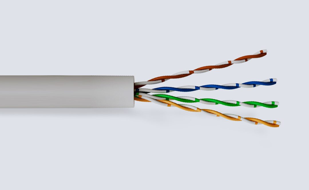
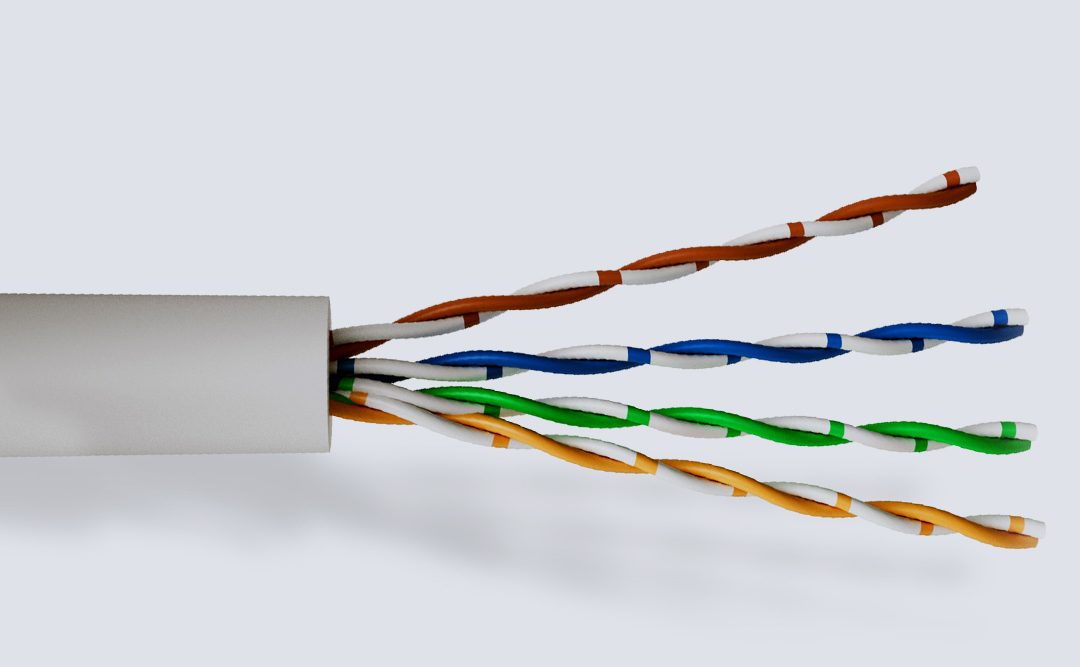
Category 5 and 6 cable, commonly referred to as cat 5e and cat 6, is a twisted pair cable for carrying signals.
These types of cable are used in structured cabling for computer networks such as Ethernet. The cable standard provides performance of up to 100 MHz and is suitable for 10BASE-T, 100BASE-TX (Fast Ethernet), and 1000BASE-T (Gigabit Ethernet). Cat 5/6 is also used to carry other signals such as telephony and video.
This cable is commonly connected using punch-down blocks and modular connectors. Most category 5/6 cables are unshielded, relying on the balanced line twisted pair design and differential signalling for noise rejection, however screened cables are also available.

Bus Cable

Cables Include: Cat 6 Cat 6A Cat 7
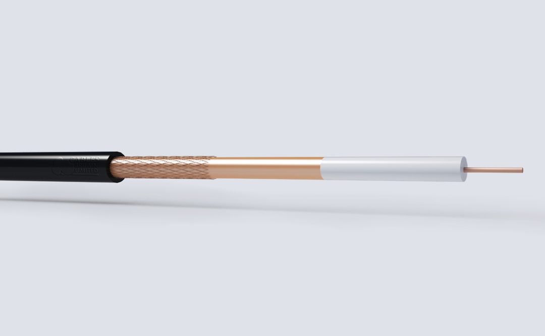

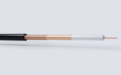
Cables Britain offer a range of cables designed for use on CCTV, Broadband Systems, Cable TV, MATV, and quality satellite reception. They are manufactured in accordance with EN50117 standards.
The cables are designed to work at frequencies in excess of 3000Mhz, whilst offering excellent attenuation and RLR figures.
The construction is Gas Injected Foam with a longitudinally overlapped copper tape and plain copper braid, facilitating good bending radius characteristics and very efficient screening in areas with high electrical noise presence.
The range is manufactured to meet the stringent CAI Construction / Performance criteria, so digital compatibility is assured.

Internal telephone cables.


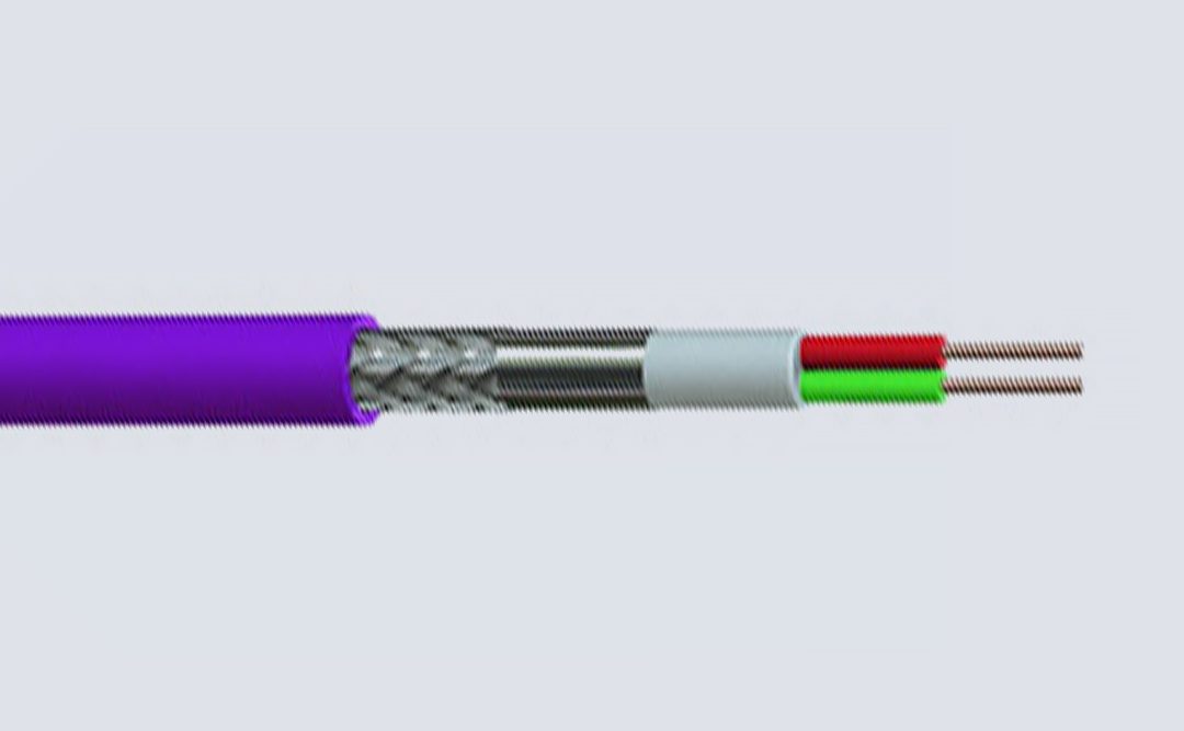
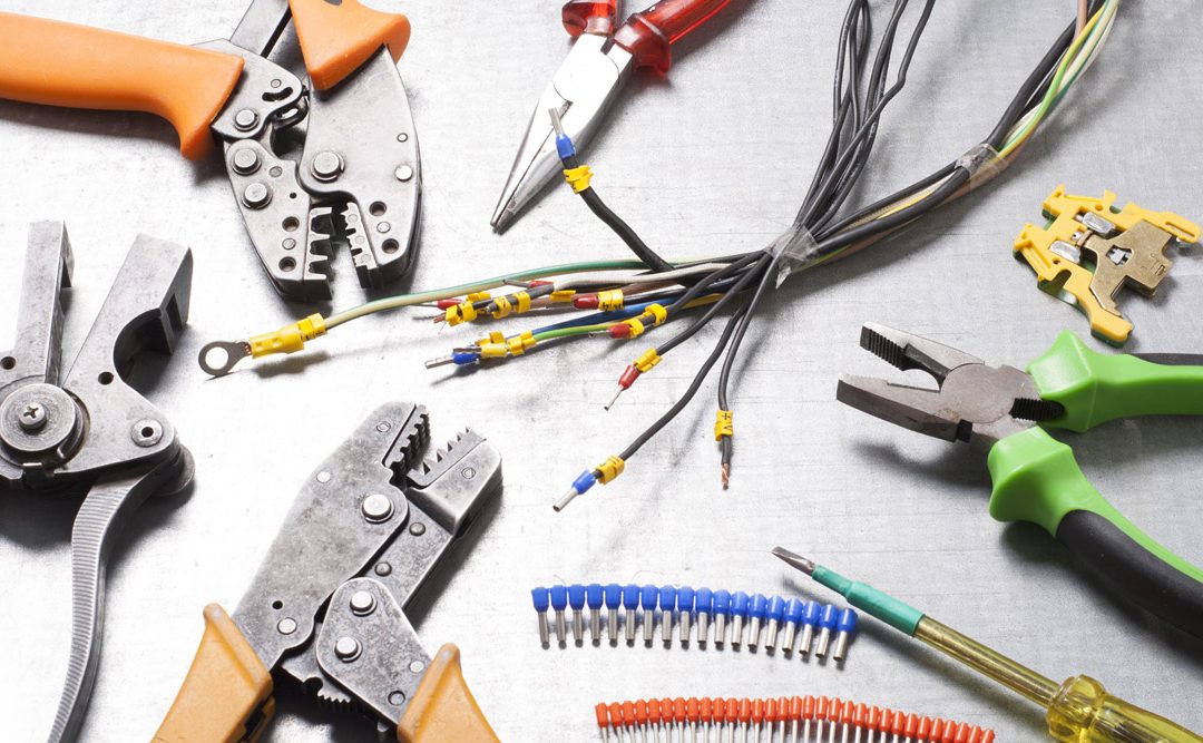
Control flex cables are designed to measure, design or regulate in the field of process automation.
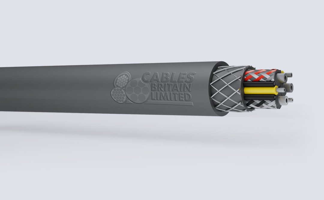
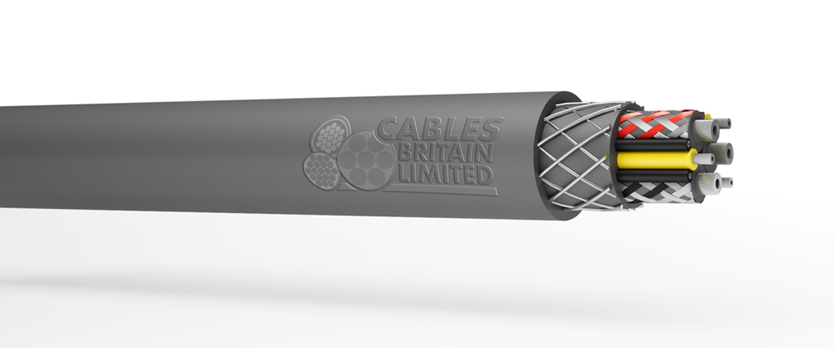
There are three different types of Control Cable in the area of process automation: CY, YY and SY Cable.
With its GSWB braid SY is suited to installations with medium to high mechanical stress. YY and CY Control Cable are very similar in construction, but without the mechanical protection provided by the steel wire.
YY is a versatile cable that works well in environments with only light mechanical stress and CY Cable has a tinned copper wire braid and polyester binder tape, which provide protection against external electromagnetic influences.
Our power cables have many accessories. For more information, don’t hesitate to call us on 0121 508 6890 or get in touch via our Contact Page.

Our power cables have many accessories. For more information, don’t hesitate to call us on 0121 508 6890 or get in touch via our Contact...
LiYCY Cable
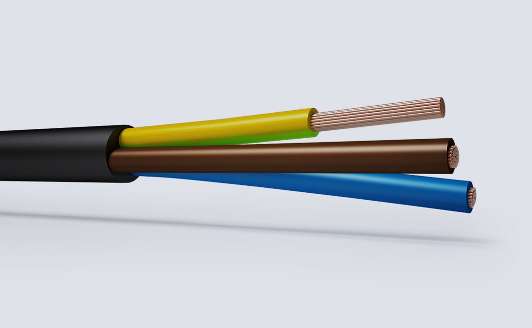
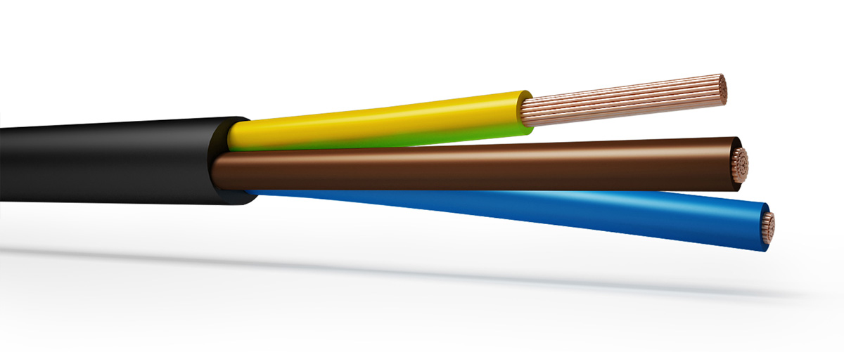
Flexible Rubber cables are robust and massively flexible designed primarily as a trailing cable for use in the supply of power for portable or mobile tools and equipment suitable to operate under light stress in dry or damp conditions.
Conductor Operating Temperature: 60°C Ambient Temperature: 30°C Conductor Operating Temperature: 60°C/85°C The above table is for 60°C...
Ambient temperature: 40ºC Conductor operating temperature: 90ºC Notes The current-carrying capacities in this appendix are based upon the following reference...
The table above is in accordance with Table 4F3A of the 17th Edition of IEE Wiring Regulations. The table above is in accordance with Table 4F3B of the 17th...
Duty Cycle and Current carrying Capacity The current carrying capacity of a welding depends on the length of the duty cycle. The duty cycle is the length of time in which a loaded current...

Instrumentation and thermocouple cables are designed not only to supply power but to monitor activity within the cable. Instrumentation cables are used to monitor electrical deviation whereas thermocouple cables measure temperature.
Our power cables have many accessories. For more information, don’t hesitate to call us on 0121 508 6890 or get in touch via our Contact Page. [ic_add_posts...
Our power cables have many accessories. For more information, don’t hesitate to call us on 0121 508 6890 or get in touch via our Contact Page. [ic_add_posts...
Our power cables have many accessories. For more information, don’t hesitate to call us on 0121 508 6890 or get in touch via our Contact Page. [ic_add_posts...
Our power cables have many accessories. For more information, don’t hesitate to call us on 0121 508 6890 or get in touch via our Contact Page. [ic_add_posts...
Our power cables have many accessories. For more information, don’t hesitate to call us on 0121 508 6890 or get in touch via our Contact Page. [ic_add_posts...
Our power cables have many accessories. For more information, don’t hesitate to call us on 0121 508 6890 or get in touch via our Contact Page. [ic_add_posts...

Our power cables have many accessories. For more information, don’t hesitate to call us on 0121 508 6890 or get in touch via our Contact Page. [ic_add_posts...
Our power cables have many accessories. For more information, don’t hesitate to call us on 0121 508 6890 or get in touch via our Contact Page. [ic_add_posts...
Our power cables have many accessories. For more information, don’t hesitate to call us on 0121 508 6890 or get in touch via our Contact Page. [ic_add_posts...
Our power cables have many accessories. For more information, don’t hesitate to call us on 0121 508 6890 or get in touch via our Contact Page. [ic_add_posts...
Our power cables have many accessories. For more information, don’t hesitate to call us on 0121 508 6890 or get in touch via our Contact Page. [ic_add_posts...
Our power cables have many accessories. For more information, don’t hesitate to call us on 0121 508 6890 or get in touch via our Contact Page. [ic_add_posts...
Our power cables have many accessories. For more information, don’t hesitate to call us on 0121 508 6890 or get in touch via our Contact Page. [ic_add_posts...
Our power cables have many accessories. For more information, don’t hesitate to call us on 0121 508 6890 or get in touch via our Contact Page. [ic_add_posts...

Our power cables have many accessories. For more information, don’t hesitate to call us on 0121 508 6890 or get in touch via our Contact Page. [ic_add_posts...
Our power cables have many accessories. For more information, don’t hesitate to call us on 0121 508 6890 or get in touch via our Contact Page. [ic_add_posts...
Our power cables have many accessories. For more information, don’t hesitate to call us on 0121 508 6890 or get in touch via our Contact Page. [ic_add_posts...
Our power cables have many accessories. For more information, don’t hesitate to call us on 0121 508 6890 or get in touch via our Contact Page. [ic_add_posts...
Our power cables have many accessories. For more information, don’t hesitate to call us on 0121 508 6890 or get in touch via our Contact Page. [ic_add_posts...
Our power cables have many accessories. For more information, don’t hesitate to call us on 0121 508 6890 or get in touch via our Contact Page. [ic_add_posts...

Low Voltage Power Cables, Aluminum and Copper conductors of voltage range:0.6/1.0 kV
Copper Conductor Cables
Aluminium Conductor Cables
Thermoplastic/ PVC Insulated Cables
Thermoset/XLPE Insulated Cables
Armoured/ Non – Armoured Cables
Single core cables up to and including 1000 mm2
2 core cables up to and including 95 mm2
3, 4 core & 4 core with reduced neutral cables up to and including 500 mm2
IEC 60502 (Part 1)”PVC/ XLPE insulated cables” single core /multi-core BS 5467 for XLPE insulated Armoured cables
BS 7889 for XLPE insulated single core unarmoured cables
BS 5467 SWA PVC 0.6/1kV Cable
BS 6724 SWA LSZH 0.6/1kV Cable


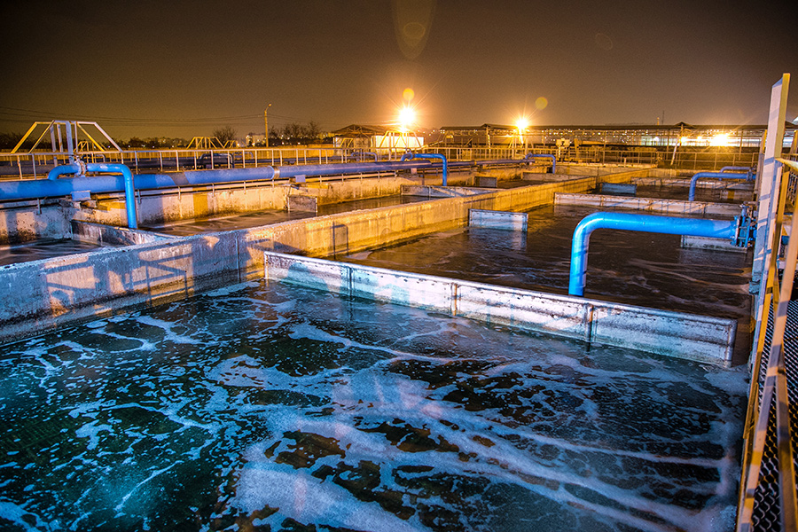
Marine, oil and petrochemical cables are designed to withstand the harsh environments associated with offshore power generation.
These cables are built to withstand high and low temperatures, salt water, acid, humidity and mud making them perfect for use aboard ships, on offshore platforms and other oil drilling and production facilities.
* Based on Standard Ambient Air Temperature of 45°C Where more than six bunched cables on cable trays, in cable conduits, pipes or trunking are...
Ambient Air Temperature of 45°C When more than six bunched cables on cable trays, in cable conduits, pipes or trunking are expected to operate ...
A number of different types of cables are used in mines. There are fixed mining cables and portable mining cables, the latter being described here.
The key requirements of portable cables are flexibility, and resistance to mechanical abrasion and damage. Due to the additional demands put on portable mining cables used for reeling and dereeling applications, special design may be required.
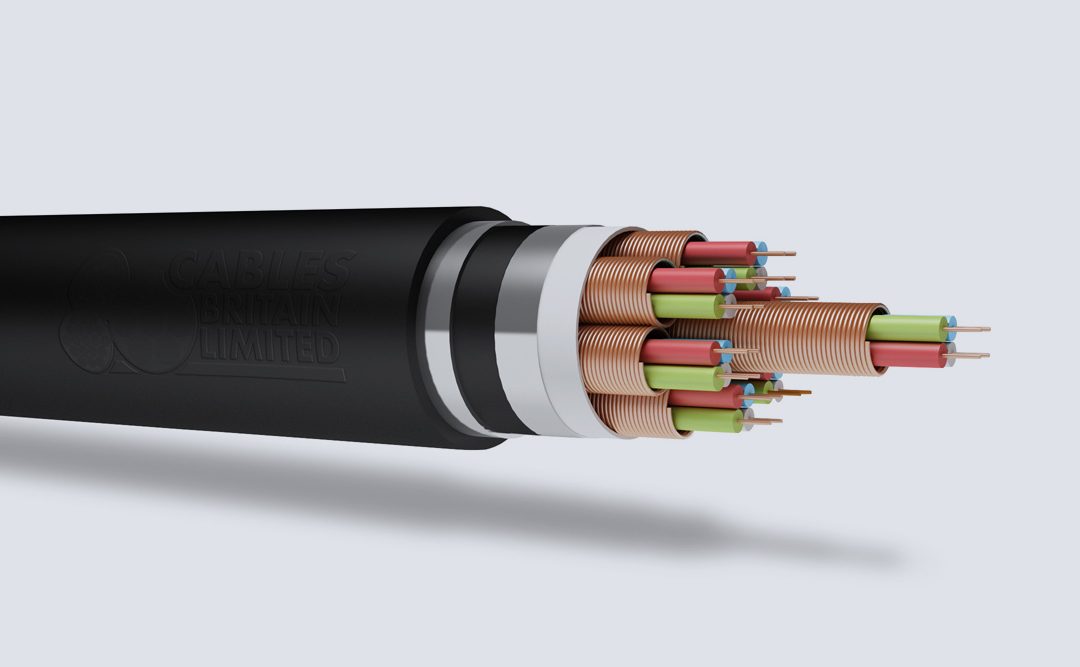
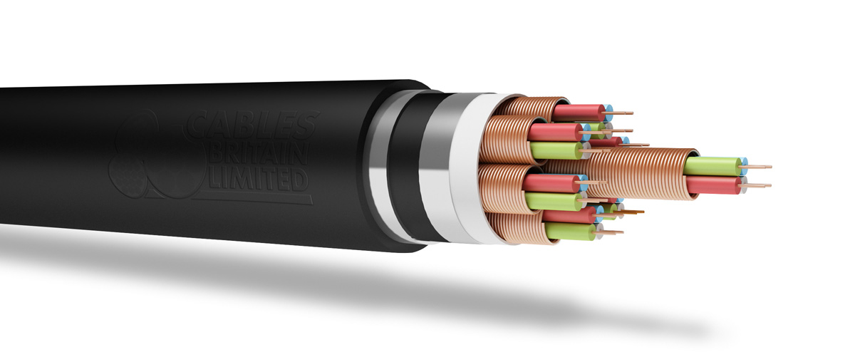
There are many types of portable mining cables. They are available in ratings up to 25 kV, and may have as many as five conductors. An example of SHD-GC Cable, is shown in the illustration. It has three insulated, shielded conductors, two bare ground wires, a ground check wire, and an overall jacket. The conductors for this cable are annealed, bare or tinned copper wires. The braided shield may be tin-coated wires, or a tin-coated copper wire/textile composite.
The grounding conductor(s) annealed, bare or tinned, stranded copper wires, and the ground check conductor is annealed, bare, stranded copper wires with EPR insulation and nylon braid, elastomeric jacket holds the conductor assembly firmly in place, to minimize snaking and cork-screwing during reeling and dereeling.
Cables Britain offer a wide range of Network Rail style cables to be used in the railway and highway industry. Our cables have been designed, tested and approved to meet the specific standards of their respective industries.
The above table is in accordance with BS EN 60228 (previously BS 6360) Our power cables have many accessories. For more information, don’t hesitate to call us on 0121 508 6890 or get in...
The above table is in accordance with BS EN 60228 (previously BS 6360) Our power cables have many accessories. For more information, don’t hesitate to call us on 0121 508 6890 or get in...
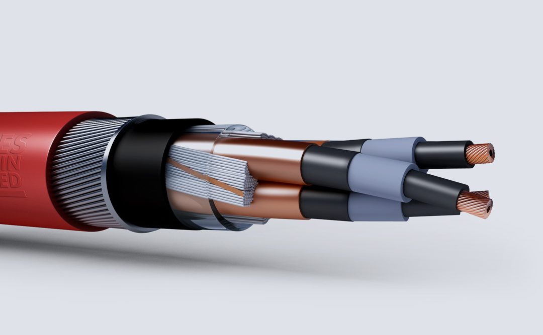

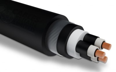
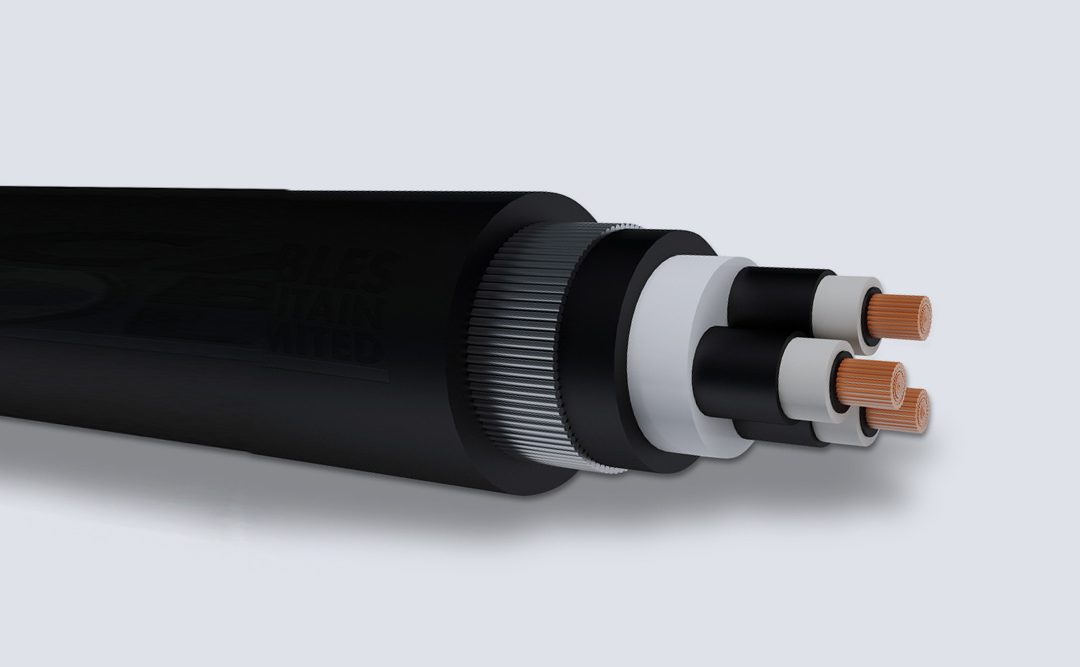
Medium power cables have voltage grade greater than 1 kV. Medium voltage usually goes up to 46 kV.
Medium Voltage distribution systems begin at substations and supply electricity to a wide spectrum of power consumers. When selecting a cable, the basic aim is to safely provide adequate electrical power, with continuous, trouble-free operation, in a system that is able to withstand unexpected demands and overload conditions. Each installation has particular requirements that must be considered. There are distinct benefits from specifying a copper-conductor cable that has been manufactured under rigid specification and quality control procedures. It will provide maximum performance with minimum maintenance. There are seven types different by construction for medium voltage copper power cables in the 1 kV to 46 kV range. Most are available in single- and multi-core configurations. There are ranges of sizes and design variations for each type.
Our power cables have many accessories. For more information, don’t hesitate to call us on 0121 508 6890 or get in touch via our Contact Page. [ic_add_posts...
Our power cables have many accessories. For more information, don’t hesitate to call us on 0121 508 6890 or get in touch via our Contact Page. [ic_add_posts...

Our power cables have many accessories. For more information, don’t hesitate to call us on 0121 508 6890 or get in touch via our Contact Page. [ic_add_posts...
Our power cables have many accessories. For more information, don’t hesitate to call us on 0121 508 6890 or get in touch via our Contact Page. [ic_add_posts...
Our power cables have many accessories. For more information, don’t hesitate to call us on 0121 508 6890 or get in touch via our Contact Page. [ic_add_posts...
Our power cables have many accessories. For more information, don’t hesitate to call us on 0121 508 6890 or get in touch via our Contact Page. [ic_add_posts...
Our power cables have many accessories. For more information, don’t hesitate to call us on 0121 508 6890 or get in touch via our Contact Page. [ic_add_posts...
Our power cables have many accessories. For more information, don’t hesitate to call us on 0121 508 6890 or get in touch via our Contact Page. [ic_add_posts...
Our power cables have many accessories. For more information, don’t hesitate to call us on 0121 508 6890 or get in touch via our Contact Page. [ic_add_posts...
Our power cables have many accessories. For more information, don’t hesitate to call us on 0121 508 6890 or get in touch via our Contact Page. [ic_add_posts...
Our power cables have many accessories. For more information, don’t hesitate to call us on 0121 508 6890 or get in touch via our Contact Page. [ic_add_posts...
Our power cables have many accessories. For more information, don’t hesitate to call us on 0121 508 6890 or get in touch via our Contact Page. [ic_add_posts...
Our power cables have many accessories. For more information, don’t hesitate to call us on 0121 508 6890 or get in touch via our Contact Page. [ic_add_posts...
Our power cables have many accessories. For more information, don’t hesitate to call us on 0121 508 6890 or get in touch via our Contact Page. [ic_add_posts...
Our power cables have many accessories. For more information, don’t hesitate to call us on 0121 508 6890 or get in touch via our Contact Page. [ic_add_posts...
Our power cables have many accessories. For more information, don’t hesitate to call us on 0121 508 6890 or get in touch via our Contact Page. [ic_add_posts...
Our power cables have many accessories. For more information, don’t hesitate to call us on 0121 508 6890 or get in touch via our Contact Page. [ic_add_posts...
Our power cables have many accessories. For more information, don’t hesitate to call us on 0121 508 6890 or get in touch via our Contact Page. [ic_add_posts...
Our power cables have many accessories. For more information, don’t hesitate to call us on 0121 508 6890 or get in touch via our Contact Page. [ic_add_posts...
Our power cables have many accessories. For more information, don’t hesitate to call us on 0121 508 6890 or get in touch via our Contact Page. [ic_add_posts...
Our power cables have many accessories. For more information, don’t hesitate to call us on 0121 508 6890 or get in touch via our Contact Page. [ic_add_posts...
Our power cables have many accessories. For more information, don’t hesitate to call us on 0121 508 6890 or get in touch via our Contact Page. [ic_add_posts...
Our power cables have many accessories. For more information, don’t hesitate to call us on 0121 508 6890 or get in touch via our Contact Page. [ic_add_posts...
Our power cables have many accessories. For more information, don’t hesitate to call us on 0121 508 6890 or get in touch via our Contact Page. [ic_add_posts...
Our power cables have many accessories. For more information, don’t hesitate to call us on 0121 508 6890 or get in touch via our Contact Page. [ic_add_posts...
Our power cables have many accessories. For more information, don’t hesitate to call us on 0121 508 6890 or get in touch via our Contact Page. [ic_add_posts...
BS 7835 XLPE LSZH 6.35/11 (12)kV Cable
BS 6622 XLPE PVC 19/33 (36)kV Cable
For more information, don’t hesitate to call us on 0121 508 6890 or get in touch via our Contact Page.


Location: TBC
Contract Value: £TBC
Scope: TBC
TBC
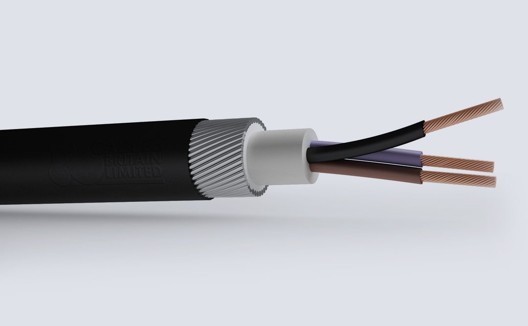
Cable construction
| Conductor | Class 2 stranded copper conductor according to BS EN 60228 |
| Insulation | XLPE (Cross-Linked Polyethylene) |
| Bedding | PVC (Polyvinyl Chloride) |
| Armour | SWA (Steel Wire Armour) |
| Sheath | PVC (Polyvinyl Chloride) |
Dimensions - BS5467 XLPE/PVC/AWA/PVC (Copper)
| No. of Cores | Nominal Cross Sectional Area mm² | Nominal Thickness of Insulation mm | Nominal Overall Diameter mm | Nominal Weight kg/km | BW / CW Gland | Wraparound Cleats | |
|---|---|---|---|---|---|---|---|
| Under Armour | Overall | ||||||
| 2 | 1.5 | 0.6 | 7.3 | 12.1 | 302 | 20 | CC5 |
| 2 | 2.5 | 0.7 | 8.5 | 13.6 | 346 | 20 | CC6 |
| 2 | 4 | 0.7 | 9.4 | 14.7 | 410 | 20S | CC7 |
| 2 | 6 | 0.7 | 10.5 | 15.9 | 499 | 20 | CC7 |
| 2 | 10 | 0.7 | 12.3 | 18 | 648 | 20 | CC8 |
| 2 | 16 | 0.7 | 14.3 | 20.4 | 978 | 20 | CC9 |
| 2 | 25 | 0.9 | 14.7 | 20.4 | 1290 | 25 | CC9 |
| 2 | 35 | 0.9 | 16.8 | 23.3 | 1500 | 25 | CC10 |
| 2 | 50 | 1 | 19 | 25.8 | 1890 | 25 | CC11 |
| 2 | 70 | 1.1 | 22 | 29 | 2450 | 32 | CC12 |
| 2 | 95 | 1.1 | 25.1 | 33.1 | 3300 | 32 | CC14 |
| 2 | 120 | 1.2 | 27.9 | 36.1 | 4020 | 40 | CC16 |
| 2 | 150 | 1.4 | 30.9 | 39.3 | 4750 | 40 | CC16 |
| 3 | 1,5 | 0.6 | 7.8 | 12.6 | 330 | 20 | CC5 |
| 3 | 2.5 | 0.7 | 9.2 | 14.1 | 390 | 20S | CC6 |
| 3 | 4 | 0.7 | 10 | 15.3 | 464 | 20S | CC7 |
| 3 | 6 | 0.7 | 11.2 | 16.6 | 568 | 20 | CC7 |
| 3 | 10 | 0.7 | 13.1 | 19.5 | 866 | 20 | CC8 |
| 3 | 16 | 0.7 | 15.3 | 21.6 | 1152 | 25 | CC9 |
| 3 | 25 | 0.9 | 18.9 | 23.6 | 1800 | 25 | CC11 |
| 3 | 35 | 0.9 | 21.3 | 25.7 | 2230 | 32 | CC12 |
| 3 | 50 | 1 | 21.7 | 28.5 | 2490 | 32 | CC12 |
| 3 | 70 | 1.1 | 25.2 | 32.2 | 3290 | 32 | CC14 |
| 3 | 95 | 1.1 | 28.8 | 37 | 4440 | 40 | CC16 |
| 3 | 120 | 1.2 | 32 | 40.4 | 5470 | 40 | CC16 |
| 3 | 150 | 1.4 | 35.9 | 45.5 | 6930 | 50S | CC18 |
| 3 | 185 | 1.6 | 40 | 49.8 | 8350 | 63S | CC20 |
| 3 | 240 | 1.7 | 44.9 | 55.1 | 10400 | 63S | - |
| 3 | 300 | 1.8 | 49.8 | 60.2 | 12600 | 63S | - |
| 3 | 400 | 2 | 55.8 | 66.6 | 14600 | 75S | - |
| 4 | 1.5 | 0.6 | 8.5 | 13.3 | 365 | 20S | CC6 |
| 4 | 2.5 | 0.7 | 9.9 | 15 | 438 | 20 | CC6 |
| 4 | 4 | 0.7 | 11 | 16.4 | 532 | 20 | CC7 |
| 4 | 6 | 0.7 | 12.3 | 18.7 | 764 | 20 | CC8 |
| 4 | 10 | 0.7 | 14.5 | 21.1 | 1013 | 25 | CC9 |
| 4 | 16 | 0.7 | 17 | 23.4 | 1360 | 25 | CC10 |
| 4 | 25 | 0.9 | 21 | 26.1 | 2160 | 32 | CC11 |
| 4 | 35 | 0.9 | 23.6 | 28.6 | 2690 | 32 | CC12 |
| 4 | 50 | 1 | 25 | 32 | 3130 | 32 | CC14 |
| 4 | 70 | 1.1 | 29.5 | 37.7 | 4500 | 40 | CC16 |
| 4 | 95 | 1.1 | 33.3 | 41.7 | 5600 | 50S | CC18 |
| 4 | 120 | 1.2 | 37.5 | 47.1 | 7400 | 50 | CC20 |
| 4 | 150 | 1.4 | 41.6 | 51.4 | 8780 | 50 | - |
| 4 | 185 | 1.6 | 46.4 | 56.6 | 10630 | 63S | - |
| 4 | 240 | 1.7 | 52.6 | 63 | 13390 | 63 | - |
| 4 | 300 | 1.8 | 58 | 68.8 | 16290 | 75S | - |
| 4 | 400 | 2 | 65.4 | 78.1 | 19800 | 90 | - |
| 5 | 1.5 | 0.6 | 9.7 | 14.3 | 410 | 20S | CC6 |
| 5 | 2.5 | 0.7 | 11.7 | 16.1 | 470 | 20 | CC7 |
| 5 | 4 | 0.7 | 13 | 17.8 | 710 | 20 | CC7 |
| 5 | 6 | 0.7 | 14.5 | 20 | 876 | 25 | CC8 |
| 5 | 10 | 0.7 | 17.2 | 22.9 | 1165 | 25 | CC10 |
| 5 | 16 | 0.7 | 20 | 26.6 | 1742 | 32 | CC11 |
| 5 | 25 | 0.9 | 24.7 | 31.5 | 2323 | 32 | CC14 |
| 5 | 35 | 0.9 | 27.8 | 34.8 | 2932 | 40 | CC14 |
| 5 | 50 | 1 | 32.4 | 40.4 | 4192 | 50S | CC16 |
| 7 | 1.5 | 0.6 | 10.2 | 15.2 | 470 | 20S | CC6 |
| 7 | 2.5 | 0.7 | 12.3 | 17.1 | 600 | 20 | CC7 |
| 7 | 4 | 0.7 | 13.6 | 19.1 | 881 | 20 | CC8 |
| 12 | 1.5 | 0.6 | 13.7 | 19.4 | 780 | 20 | CC8 |
| 12 | 2.5 | 0.7 | 16.3 | 22.4 | 1000 | 25 | CC9 |
| 19 | 1.5 | 0.6 | 16.2 | 22.2 | 1000 | 25 | CC9 |
| 19 | 2.5 | 0.7 | 19.9 | 26.6 | 1540 | 25 | CC11 |
| 27 | 1.5 | 0.6 | 20 | 26.7 | 1500 | 32 | CC11 |
| 27 | 2.5 | 0.7 | 24 | 30.7 | 1950 | 32 | CC14 |
| 37 | 1.5 | 0.6 | 22.3 | 29 | 1800 | 32 | CC12 |
| 37 | 2.5 | 0.7 | 26.9 | 33.8 | 2350 | 40 | CC14 |
| Nominal Cross Sectional Area mm² | Minimum No. Of Wires In Conductor | Maximum Resistance of Conductor At 20ºC | |||||
|---|---|---|---|---|---|---|---|
| Circular | Circular Compacted | Shaped | Annealed Copper Conductor | ||||
| Cu | Al | Cu | Al | Cu | Al | Plain Wires ohms/km | |
| 1.5 | 7 | - | 6 | - | - | - | 12.1 |
| 2.5 | 7 | - | 6 | - | - | - | 7.41 |
| 4 | 7 | - | 6 | - | - | - | 4.61 |
| 6 | 7 | - | 6 | - | - | - | 3.08 |
| 10 | 7 | 7 | 6 | 6 | - | - | 1.83 |
| 16 | 7 | 7 | 6 | 6 | - | - | 1.15 |
| 25 | 7 | 7 | 6 | 6 | 6 | 6 | 0.727 |
| 35 | 7 | 7 | 6 | 6 | 6 | 6 | 0.524 |
| 50 | 19 | 19 | 6 | 6 | 6 | 6 | 0.387 |
| 70 | 19 | 19 | 12 | 12 | 12 | 12 | 0.268 |
| 95 | 19 | 19 | 15 | 15 | 15 | 15 | 0.193 |
| 120 | 37 | 37 | 18 | 15 | 18 | 15 | 0.153 |
| 150 | 37 | 37 | 18 | 15 | 18 | 15 | 0.124 |
| 185 | 37 | 37 | 30 | 30 | 30 | 30 | 0.0991 |
| 240 | 37 | 37 | 34 | 30 | 34 | 30 | 0.0754 |
| 300 | 61 | 61 | 34 | 30 | 34 | 30 | 0.0601 |
| 400 | 61 | 61 | 53 | 53 | 53 | 53 | 0.047 |
| Nominal Cross Sectional Area mm² | Reference Method C (Clipped Direct) | Reference Method E (In Free Air or on a Perforated Cable Tray, Horizontal or Vertical) | Reference Method D (direct in ground or in ducting in ground, in or around Buildings) | |||
|---|---|---|---|---|---|---|
| 1 Two Core Cable Single-Phase AC or DC | 1 Three or 1 Four core cable Three-phase AC | 1 Two core cable Single-Phase AC or DC | 1 Three or 1 Four core cable Three-Phase AC | 1 Two core cable single-phase AC or DC | 1 Three or 1 Four core cable three-phase AC | |
| 1.5 | 27 | 23 | 29 | 25 | 25 | 21 |
| 2.5 | 36 | 31 | 39 | 33 | 33 | 28 |
| 4 | 49 | 42 | 52 | 44 | 43 | 36 |
| 6 | 62 | 53 | 66 | 56 | 53 | 44 |
| 10 | 85 | 73 | 90 | 78 | 71 | 58 |
| 16 | 110 | 94 | 115 | 99 | 91 | 75 |
| 25 | 146 | 124 | 152 | 131 | 116 | 96 |
| 35 | 180 | 154 | 188 | 162 | 139 | 115 |
| 50 | 219 | 187 | 228 | 197 | 164 | 135 |
| 70 | 279 | 238 | 291 | 251 | 203 | 167 |
| 95 | 338 | 289 | 354 | 304 | 239 | 197 |
| 120 | 392 | 335 | 410 | 353 | 271 | 223 |
| 150 | 451 | 386 | 472 | 406 | 306 | 251 |
| 185 | 515 | 441 | 539 | 463 | 343 | 281 |
| 240 | 607 | 520 | 636 | 546 | 395 | 324 |
| 300 | 698 | 599 | 732 | 628 | 446 | 365 |
| 400 | 787 | 673 | 847 | 728 | - | - |
Ambient temperature: 30ºC
Conductor operating temperature: 90ºC
Notes
1. Where a conductor operates at a temperature exceeding 70ºC it must be ascertained that the equipment connected to the conductor is suitable for the conductor operating
temperature (see Regulation 512.1.2 of the 17th Edition of IEE Wiring Regulations).
2. Where cables in this table are connected to equipment or accessories designed to operate at a temperature not exceeding 70ºC , the current ratings given in the equivalent
table for 70ºC thermoplastic insulated cables (Table 4D3A) must be used (see Regulation 523.1 of the 17th Edition of IEE Wiring Regulations).
The above table is in accordance with Table 4E3A of the 17th Edition of IEE Wiring Regulations.
Voltage Drop
| Nominal Cross Sectional Area mm² | Two Core Cable DC | Two Core Cable Single-Phase AC mV/A/m | Three Or Four Core Cable Three-Phase AC mV/A/m | ||||
|---|---|---|---|---|---|---|---|
| 1.5 | 31 | 31 | 27 | ||||
| 2.5 | 19 | 19 | 16 | ||||
| 4 | 12 | 12 | 10 | ||||
| 6 | 7.9 | 7.9 | 6.8 | ||||
| 10 | 4.7 | 4.7 | 4 | ||||
| 16 | 2.9 | 2.9 | 2.5 | ||||
| r | x | z | r | x | z | ||
| 25 | 1.85 | 1.85 | 0.160 | 1.900 | 1.600 | 0.140 | 1.650 |
| 35 | 1.35 | 1.35 | 0.155 | 1.350 | 1.150 | 0.135 | 1.150 |
| 50 | 0,98 | 0.99 | 0.155 | 1.000 | 0.860 | 0.135 | 0.870 |
| 70 | 0.67 | 0.67 | 0.150 | 0.690 | 0.590 | 0.130 | 0.600 |
| 95 | 0.49 | 0.50 | 0.150 | 0.520 | 0.430 | 0.130 | 0.450 |
| 120 | 0.39 | 0.40 | 0.145 | 0.420 | 0.340 | 0.130 | 0.370 |
| 150 | 0.31 | 0.32 | 0.145 | 0.350 | 0.280 | 0.125 | 0.300 |
| 185 | 0.25 | 0.26 | 0.145 | 0.290 | 0.220 | 0.125 | 0.260 |
| 240 | 0.195 | 0.20 | 0.140 | 0.240 | 0.175 | 0.125 | 0.120 |
| 300 | 0.115 | 0.16 | 0.140 | 0.210 | 0.140 | 0.120 | 0.185 |
| 400 | 0.12 | 0.13 | 0.140 | 0.190 | 0.115 | 0.120 | 0.165 |
Conductor operating temperature: 90ºC
r = Resistive Component
x = Reactive Component
z = Impedance Value
For cables having conductors of 16mm2 or less cross sectional area their inductances can be ignored and (mV/A/m)r values only are tabulated. For cables having conductors greater than 16mm2, cross sectional area the impedance values are given as (mV/A/m)z, together with the resistive component (mV/A/m)r and the reactive component (mV/A/m)x.
The above paragraph is extracted from Appendix 4 of the 17th Edition of IEE Wiring Regulations.
.
For more information, don’t hesitate to call us on 0121 508 6890 or get in touch via our Contact Page.
BS 5467 SWA PVC 0.6/1kV Cable BS 6724 SWA LSZH 0.6/1kV CableBS 5467 SWA PVC 0.6/1kV Cable
Posted in Power Generation, LV Power & General Wiring Cable Comments Off on BS 5467 SWA PVC 0.6/1kV Cable BS 6724 SWA LSZH 0.6/1kV Cable
Posted in Power Generation, LV Power & General Wiring Cable Comments Off on BS 6724 SWA LSZH 0.6/1kV Cable
Cable construction
| Conductor | Class 2 stranded copper conductor according to BS EN 60228 |
| Insulation | XLPE (Cross-Linked Polyethylene) |
| Bedding | LSZH (Low Smoke Zero Halogen) Type LTS1 according to BS 7655 |
| Armour | SWA (Steel Wire Armour) |
| Sheath | LSZH (Low Smoke Zero Halogen) Type LTS1 according to BS 7655 |
Dimensions - BS6724 XLPE/LSZH/SWA/LSZH (Copper)
| No. of Cores | Nominal Cross Sectional Area mm² | Nominal Thickness of Insulation mm | Nominal Overall Diameter mm | Nominal Weight kg/km | BW / CW Gland | Wraparound Cleats | |
|---|---|---|---|---|---|---|---|
| Under Armour | Overall | ||||||
| 2 | 1.5 | 0.6 | 7.3 | 12.1 | 302 | 20 | CC5 |
| 2 | 2.5 | 0.7 | 8.5 | 13.6 | 346 | 20 | CC6 |
| 2 | 4 | 0.7 | 9.4 | 14.7 | 410 | 20S | CC7 |
| 2 | 6 | 0.7 | 10.5 | 15.9 | 499 | 20 | CC7 |
| 2 | 10 | 0.7 | 12.3 | 18 | 648 | 20 | CC8 |
| 2 | 16 | 0.7 | 14.3 | 20.4 | 978 | 20 | CC9 |
| 2 | 25 | 0.9 | 14.7 | 20.4 | 1290 | 25 | CC9 |
| 2 | 35 | 0.9 | 16.8 | 23.3 | 1500 | 25 | CC10 |
| 2 | 50 | 1 | 19 | 25.8 | 1890 | 25 | CC11 |
| 2 | 70 | 1.1 | 22 | 29 | 2450 | 32 | CC12 |
| 2 | 95 | 1.1 | 25.1 | 33.1 | 3300 | 32 | CC14 |
| 2 | 120 | 1.2 | 27.9 | 36.1 | 4020 | 40 | CC16 |
| 2 | 150 | 1.4 | 30.9 | 39.3 | 4750 | 40 | CC16 |
| 3 | 1,5 | 0.6 | 7.8 | 12.6 | 330 | 20 | CC5 |
| 3 | 2.5 | 0.7 | 9.2 | 14.1 | 390 | 20S | CC6 |
| 3 | 4 | 0.7 | 10 | 15.3 | 464 | 20S | CC7 |
| 3 | 6 | 0.7 | 11.2 | 16.6 | 568 | 20 | CC7 |
| 3 | 10 | 0.7 | 13.1 | 19.5 | 866 | 20 | CC8 |
| 3 | 16 | 0.7 | 15.3 | 21.6 | 1152 | 25 | CC9 |
| 3 | 25 | 0.9 | 18.9 | 23.6 | 1800 | 25 | CC11 |
| 3 | 35 | 0.9 | 21.3 | 25.7 | 2230 | 32 | CC12 |
| 3 | 50 | 1 | 21.7 | 28.5 | 2490 | 32 | CC12 |
| 3 | 70 | 1.1 | 25.2 | 32.2 | 3290 | 32 | CC14 |
| 3 | 95 | 1.1 | 28.8 | 37 | 4440 | 40 | CC16 |
| 3 | 120 | 1.2 | 32 | 40.4 | 5470 | 40 | CC16 |
| 3 | 150 | 1.4 | 35.9 | 45.5 | 6930 | 50S | CC18 |
| 3 | 185 | 1.6 | 40 | 49.8 | 8350 | 63S | CC20 |
| 3 | 240 | 1.7 | 44.9 | 55.1 | 10400 | 63S | - |
| 3 | 300 | 1.8 | 49.8 | 60.2 | 12600 | 63S | - |
| 3 | 400 | 2 | 55.8 | 66.6 | 14600 | 75S | - |
| 4 | 1.5 | 0.6 | 8.5 | 13.3 | 365 | 20S | CC6 |
| 4 | 2.5 | 0.7 | 9.9 | 15 | 438 | 20 | CC6 |
| 4 | 4 | 0.7 | 11 | 16.4 | 532 | 20 | CC7 |
| 4 | 6 | 0.7 | 12.3 | 18.7 | 764 | 20 | CC8 |
| 4 | 10 | 0.7 | 14.5 | 21.1 | 1013 | 25 | CC9 |
| 4 | 16 | 0.7 | 17 | 23.4 | 1360 | 25 | CC10 |
| 4 | 25 | 0.9 | 21 | 26.1 | 2160 | 32 | CC11 |
| 4 | 35 | 0.9 | 23.6 | 28.6 | 2690 | 32 | CC12 |
| 4 | 50 | 1 | 25 | 32 | 3130 | 32 | CC14 |
| 4 | 70 | 1.1 | 29.5 | 37.7 | 4500 | 40 | CC16 |
| 4 | 95 | 1.1 | 33.3 | 41.7 | 5600 | 50S | CC18 |
| 4 | 120 | 1.2 | 37.5 | 47.1 | 7400 | 50 | CC20 |
| 4 | 150 | 1.4 | 41.6 | 51.4 | 8780 | 50 | - |
| 4 | 185 | 1.6 | 46.4 | 56.6 | 10630 | 63S | - |
| 4 | 240 | 1.7 | 52.6 | 63 | 13390 | 63 | - |
| 4 | 300 | 1.8 | 58 | 68.8 | 16290 | 75S | - |
| 4 | 400 | 2 | 65.4 | 78.1 | 19800 | 90 | - |
| 5 | 1.5 | 0.6 | 9.7 | 14.3 | 410 | 20S | CC6 |
| 5 | 2.5 | 0.7 | 11.7 | 16.1 | 470 | 20 | CC7 |
| 5 | 4 | 0.7 | 13 | 17.8 | 710 | 20 | CC7 |
| 5 | 6 | 0.7 | 14.5 | 20 | 876 | 25 | CC8 |
| 5 | 10 | 0.7 | 17.2 | 22.9 | 1165 | 25 | CC10 |
| 5 | 16 | 0.7 | 20 | 26.6 | 1742 | 32 | CC11 |
| 5 | 25 | 0.9 | 24.7 | 31.5 | 2323 | 32 | CC14 |
| 5 | 35 | 0.9 | 27.8 | 34.8 | 2932 | 40 | CC14 |
| 5 | 50 | 1 | 32.4 | 40.4 | 4192 | 50S | CC16 |
| 7 | 1.5 | 0.6 | 10.2 | 15.2 | 470 | 20S | CC6 |
| 7 | 2.5 | 0.7 | 12.3 | 17.1 | 600 | 20 | CC7 |
| 7 | 4 | 0.7 | 13.6 | 19.1 | 881 | 20 | CC8 |
| 12 | 1.5 | 0.6 | 13.7 | 19.4 | 780 | 20 | CC8 |
| 12 | 2.5 | 0.7 | 16.3 | 22.4 | 1000 | 25 | CC9 |
| 19 | 1.5 | 0.6 | 16.2 | 22.2 | 1000 | 25 | CC9 |
| 19 | 2.5 | 0.7 | 19.9 | 26.6 | 1540 | 25 | CC11 |
| 27 | 1.5 | 0.6 | 20 | 26.7 | 1500 | 32 | CC11 |
| 27 | 2.5 | 0.7 | 24 | 30.7 | 1950 | 32 | CC14 |
| 37 | 1.5 | 0.6 | 22.3 | 29 | 1800 | 32 | CC12 |
| 37 | 2.5 | 0.7 | 26.9 | 33.8 | 2350 | 40 | CC14 |
| Nominal Cross Sectional Area mm² | Minimum No. Of Wires In Conductor | Maximum Resistance of Conductor At 20ºC | |||||
|---|---|---|---|---|---|---|---|
| Circular | Circular Compacted | Shaped | Annealed Copper Conductor | ||||
| Cu | Al | Cu | Al | Cu | Al | Plain Wires ohms/km | |
| 1.5 | 7 | - | 6 | - | - | - | 12.1 |
| 2.5 | 7 | - | 6 | - | - | - | 7.41 |
| 4 | 7 | - | 6 | - | - | - | 4.61 |
| 6 | 7 | - | 6 | - | - | - | 3.08 |
| 10 | 7 | 7 | 6 | 6 | - | - | 1.83 |
| 16 | 7 | 7 | 6 | 6 | - | - | 1.15 |
| 25 | 7 | 7 | 6 | 6 | 6 | 6 | 0.727 |
| 35 | 7 | 7 | 6 | 6 | 6 | 6 | 0.524 |
| 50 | 19 | 19 | 6 | 6 | 6 | 6 | 0.387 |
| 70 | 19 | 19 | 12 | 12 | 12 | 12 | 0.268 |
| 95 | 19 | 19 | 15 | 15 | 15 | 15 | 0.193 |
| 120 | 37 | 37 | 18 | 15 | 18 | 15 | 0.153 |
| 150 | 37 | 37 | 18 | 15 | 18 | 15 | 0.124 |
| 185 | 37 | 37 | 30 | 30 | 30 | 30 | 0.0991 |
| 240 | 37 | 37 | 34 | 30 | 34 | 30 | 0.0754 |
| Nominal Cross Sectional Area mm² | Reference Method C (Clipped Direct) | Reference Method E (In Free Air or on a Perforated Cable Tray, Horizontal or Vertical) | Reference Method D (direct in ground or in ducting in ground, in or around Buildings) | |||
|---|---|---|---|---|---|---|
| 1 Two Core Cable Single-Phase AC or DC | 1 Three or 1 Four core cable Three-phase AC | 1 Two core cable Single-Phase AC or DC | 1 Three or 1 Four core cable Three-Phase AC | 1 Two core cable single-phase AC or DC | 1 Three or 1 Four core cable three-phase AC | |
| 1.5 | 27 | 23 | 29 | 25 | 25 | 21 |
| 2.5 | 36 | 31 | 39 | 33 | 33 | 28 |
| 4 | 49 | 42 | 52 | 44 | 43 | 36 |
| 6 | 62 | 53 | 66 | 56 | 53 | 44 |
| 10 | 85 | 73 | 90 | 78 | 71 | 58 |
| 16 | 110 | 94 | 115 | 99 | 91 | 75 |
| 25 | 146 | 124 | 152 | 131 | 116 | 96 |
| 35 | 180 | 154 | 188 | 162 | 139 | 115 |
| 50 | 219 | 187 | 228 | 197 | 164 | 135 |
| 70 | 279 | 238 | 291 | 251 | 203 | 167 |
| 95 | 338 | 289 | 354 | 304 | 239 | 197 |
| 120 | 392 | 335 | 410 | 353 | 271 | 223 |
| 150 | 451 | 386 | 472 | 406 | 306 | 251 |
| 185 | 515 | 441 | 539 | 463 | 343 | 281 |
| 240 | 607 | 520 | 636 | 546 | 395 | 324 |
| 300 | 698 | 599 | 732 | 628 | 446 | 365 |
| 400 | 787 | 673 | 847 | 728 | - | - |
Ambient temperature: 30ºC
Conductor operating temperature: 90ºC
Notes
1. Where a conductor operates at a temperature exceeding 70ºC it must be ascertained that the equipment connected to the conductor is suitable for the conductor operating
temperature (see Regulation 512.1.2 of the 17th Edition of IEE Wiring Regulations).
2. Where cables in this table are connected to equipment or accessories designed to operate at a temperature not exceeding 70ºC , the current ratings given in the equivalent
table for 70ºC thermoplastic insulated cables (Table 4D3A) must be used (see Regulation 523.1 of the 17th Edition of IEE Wiring Regulations).
The above table is in accordance with Table 4E3A of the 17th Edition of IEE Wiring Regulations.
Voltage Drop
| Nominal Cross Sectional Area mm² | Two Core Cable DC | Two Core Cable Single-Phase AC mV/A/m | Three Or Four Core Cable Three-Phase AC mV/A/m | ||||
|---|---|---|---|---|---|---|---|
| 1.5 | 31 | 31 | 27 | ||||
| 2.5 | 19 | 19 | 16 | ||||
| 4 | 12 | 12 | 10 | ||||
| 6 | 7.9 | 7.9 | 6.8 | ||||
| 10 | 4.7 | 4.7 | 4 | ||||
| 16 | 2.9 | 2.9 | 2.5 | ||||
| r | x | z | r | x | z | ||
| 25 | 1.85 | 1.85 | 0.160 | 1.900 | 1.600 | 0.140 | 1.650 |
| 35 | 1.35 | 1.35 | 0.155 | 1.350 | 1.150 | 0.135 | 1.150 |
| 50 | 0,98 | 0.99 | 0.155 | 1.000 | 0.860 | 0.135 | 0.870 |
| 70 | 0.67 | 0.67 | 0.150 | 0.690 | 0.590 | 0.130 | 0.600 |
| 95 | 0.49 | 0.50 | 0.150 | 0.520 | 0.430 | 0.130 | 0.450 |
| 120 | 0.39 | 0.40 | 0.145 | 0.420 | 0.340 | 0.130 | 0.370 |
| 150 | 0.31 | 0.32 | 0.145 | 0.350 | 0.280 | 0.125 | 0.300 |
| 185 | 0.25 | 0.26 | 0.145 | 0.290 | 0.220 | 0.125 | 0.260 |
| 240 | 0.195 | 0.20 | 0.140 | 0.240 | 0.175 | 0.125 | 0.120 |
| 300 | 0.115 | 0.16 | 0.140 | 0.210 | 0.140 | 0.120 | 0.185 |
| 400 | 0.12 | 0.13 | 0.140 | 0.190 | 0.115 | 0.120 | 0.165 |
Conductor operating temperature: 90ºC
r = Resistive Component
x = Reactive Component
z = Impedance Value
* Spacings larger than one cable diameter will result in a larger voltage drop.
The above table is in accordance with Table 4E3B of the 17th Edition of IEE Wiring Regulations.
For cables having conductors of 16mm2 or less cross sectional area their inductances can be ignored and (mV/A/m)r values only are tabulated. For cables having conductors
greater than 16mm2, cross sectional area the impedance values are given as (mV/A/m)z, together with the resistive component (mV/A/m)r and the reactive component
(mV/A/m)x.
The above paragraph is extracted from Appendix 4 of the 17th Edition of IEE Wiring Regulations.
For more information, don’t hesitate to call us on 0121 508 6890 or get in touch via our Contact Page.
BS 5467 SWA PVC 0.6/1kV Cable BS 6724 SWA LSZH 0.6/1kV CableBS 5467 SWA PVC 0.6/1kV Cable
Posted in Power Generation, LV Power & General Wiring Cable Comments Off on BS 5467 SWA PVC 0.6/1kV Cable BS 6724 SWA LSZH 0.6/1kV Cable
Posted in Power Generation, LV Power & General Wiring Cable Comments Off on BS 6724 SWA LSZH 0.6/1kV Cable
Cable construction
| Conductor | Class 2 stranded copper conductor according to BS EN 60228 |
| Conductor screen | Semi-conductive XLPE (Cross-Linked Polyethylene) |
| Insulation | XLPE (Cross-Linked Polyethylene) |
| Insulation screen | Semi-conductive XLPE (Cross-Linked Polyethylene) |
| Metallic screen | Individual or overall copper tape screen according to BS 6622 |
| Filler | PET (Polyethylene Terephthalate) fibres |
| Separator | Binding tape |
| Bedding | LSZH (Low Smoke Zero Halogen) |
| Armour | Single core: AWA (Aluminium Wire Armoured) Multi-core: SWA (Steel Wire Armoured) |
| Sheath | LSZH (Low Smoke Zero Halogen) |
Dimensions
| No. of Cores | Nominal Cross Sectional Area mm² | Nominal Diameter | Nominal Weight kg/km | ||
|---|---|---|---|---|---|
| Under Armour | Over Armour | Overall | |||
| 1 | 50 | 21.7 | 24.9 | 28.5 | 1200 |
| 1 | 70 | 23 | 26.2 | 30 | 1500 |
| 1 | 95 | 24.7 | 27.9 | 31.7 | 1600 |
| 1 | 120 | 26.7 | 29.9 | 33.9 | 2100 |
| 1 | 150 | 27.5 | 31.5 | 35.7 | 2500 |
| 1 | 185 | 29.3 | 33.3 | 37.5 | 2900 |
| 1 | 240 | 31.6 | 35.6 | 40 | 3600 |
| 1 | 300 | 34.6 | 38.6 | 43 | 4300 |
| 1 | 400 | 37 | 41 | 45.8 | 5200 |
| 1 | 500 | 40.5 | 45.5 | 50.5 | 6500 |
| 1 | 630 | 44.6 | 49.6 | 54.8 | 8000 |
| 1 | 800 | 48.8 | 53.8 | 59.2 | 9850 |
| 1 | 1000 | 53.5 | 58.5 | 64.3 | 12100 |
| 3 | 25 | 39 | 44 | 48.8 | 4300 |
| 3 | 35 | 41.6 | 46.6 | 51.6 | 4700 |
| 3 | 50 | 44.4 | 49.4 | 54.6 | 5300 |
| 3 | 70 | 48.1 | 51.3 | 58.5 | 6300 |
| 3 | 95 | 52 | 57 | 62.6 | 7300 |
| 3 | 120 | 55.6 | 60.0 | 66.6 | 8400 |
| 3 | 150 | 58.6 | 63.6 | 69.8 | 9600 |
| 3 | 185 | 62.7 | 67.7 | 74.1 | 11000 |
| 3 | 240 | 68.1 | 74.4 | 81.2 | 14000 |
| 3 | 300 | 73.5 | 79.8 | 87 | 16600 |
| Nominal Cross Sectional Area mm² | Minimum No. Of Wires In Conductor | Maximum Resistance of Conductor At 20ºC | |||||
|---|---|---|---|---|---|---|---|
| Circular | Circular Compacted | Shaped | Annealed Copper Conductor | ||||
| Cu | Al | Cu | Al | Cu | Al | Plain Wires ohms/km | |
| 50 | 19 | 19 | 6 | 6 | 6 | 6 | 0.387 |
| 70 | 19 | 19 | 12 | 12 | 12 | 12 | 0.268 |
| 95 | 19 | 19 | 15 | 15 | 15 | 15 | 0.193 |
| 120 | 37 | 37 | 18 | 15 | 18 | 15 | 0.153 |
| 150 | 37 | 37 | 18 | 15 | 18 | 15 | 0.124 |
| 185 | 37 | 37 | 30 | 30 | 30 | 30 | 0.0991 |
| 240 | 37 | 37 | 34 | 30 | 34 | 30 | 0.0754 |
| 300 | 61 | 61 | 34 | 30 | 34 | 30 | 0.0601 |
| 400 | 61 | 61 | 53 | 53 | 53 | 53 | 0.047 |
| 630 | 91 | 91 | 53 | 53 | 53 | 53 | 0.0283 |
| 800 | 91 | 91 | 53 | 53 | - | - | 0.0221 |
| 1000 | 91 | 91 | 53 | 53 | - | - | 0.0176 |
| Nominal Cross Sectional Area mm² | Continuous Current Rating | |||||
|---|---|---|---|---|---|---|
| In Ground Amps | In Ducts Amps | In Air Amps | ||||
| Trefoil | Flat | Trefoil | Flat | Trefoil | Flat | |
| 50 | 220 | 230 | 220 | 220 | 250 | 300 |
| 70 | 270 | 280 | 260 | 270 | 310 | 370 |
| 95 | 320 | 335 | 305 | 325 | 375 | 460 |
| 120 | 360 | 380 | 340 | 370 | 430 | 530 |
| 150 | 410 | 430 | 375 | 410 | 490 | 600 |
| 185 | 455 | 485 | 410 | 460 | 550 | 690 |
| 240 | 520 | 560 | 470 | 540 | 650 | 820 |
| 300 | 580 | 640 | 500 | 610 | 740 | 940 |
| 400 | 650 | 730 | 530 | 690 | 840 | 1100 |
| 500 | 710 | 830 | 570 | 780 | 930 | 1280 |
| 630 | 760 | 940 | 620 | 890 | 1040 | 1480 |
| 800 | 810 | 1060 | 660 | 990 | 1140 | 1690 |
| 1000 | 860 | 1170 | 690 | 190 | 1230 | 1900 |
| 25 | 140 | 140 | 125 | 125 | 145 | 145 |
| 35 | 170 | 170 | 150 | 150 | 175 | 175 |
| 50 | 210 | 210 | 180 | 180 | 220 | 220 |
| 70 | 250 | 250 | 215 | 215 | 270 | 270 |
| 95 | 300 | 300 | 255 | 255 | 330 | 330 |
| 120 | 340 | 340 | 290 | 290 | 380 | 380 |
| 150 | 380 | 380 | 330 | 330 | 430 | 430 |
| 185 | 430 | 430 | 370 | 370 | 490 | 490 |
| 240 | 500 | 500 | 430 | 430 | 570 | 570 |
| 300 | 540 | 540 | 470 | 470 | 650 | 650 |
| Air Temperature °C | 25 | 30 | 35 | 40 | 45 | 50 | 55 |
| DE-RATING FACTOR | 1.00 | 0.96 | 0.92 | 0.88 | 0.83 | 0.78 | 0.73 |
| Ground Temperature | 10 | 15 | 20 | 25 | 30 | 35 | 40 |
| DE-RATING FACTOR | 1.03 | 1.00 | 0.97 | 0.93 | 0.89 | 0.86 | 0.82 |
| Ground Thermal Resistivity | 0.9 | 1.0 | 1.2 | 1.5 | 2.0 | 2.5 | 3.0 |
| DE-RATING FACTOR | 1.06 | 1.04 | 1.00 | 0.92 | 0.82 | 0.74 | 0.68 |
| Depth Of Laying | 0.80 | 1.00 | 1.25 | 1.50 | 1.75 | 2.0 | 2.50 |
| DE-RATING FACTOR | 1.00 | 0.97 | 0.95 | 0.94 | 0.93 | 0.91 | 0.90 |
For more information, don’t hesitate to call us on 0121 508 6890 or get in touch via our Contact Page.
BS 7835 XLPE LSZH 6.35/11 (12)kV Cable BS 6622 XLPE PVC 19/33 (36)kV CableNA2XS(FL)2Y Aluminium Conductor XLPE PE- 18/30 (36)kV Cable
Posted in Power Generation, Power Medium Voltage Cable Comments Off on NA2XS(FL)2Y Aluminium Conductor XLPE PE- 18/30 (36)kV Cable NA2XS(FL)2Y Aluminium Conductor XLPE PE-12/20 (24)kV Cable
Posted in Power Generation, Power Medium Voltage Cable Comments Off on NA2XS(FL)2Y Aluminium Conductor XLPE PE-12/20 (24)kV Cable NA2XS(FL)2Y Aluminium conductor XLPE PE-6/10 (12)kV Cable
Posted in Power Generation, Power Medium Voltage Cable Comments Off on NA2XS(FL)2Y Aluminium conductor XLPE PE-6/10 (12)kV Cable NA2XS(F)2Y Aluminium Conductor XLPE PE – 18/30k (36)V Cable
Posted in Power Generation, Power Medium Voltage Cable Comments Off on NA2XS(F)2Y Aluminium Conductor XLPE PE – 18/30k (36)V Cable NA2XS(F)2Y Aluminium Conductor XLPE PE – 12/20 (24)kV Cable
Posted in Power Generation, Power Medium Voltage Cable Comments Off on NA2XS(F)2Y Aluminium Conductor XLPE PE – 12/20 (24)kV Cable NA2XS(F)2Y Aluminium Conductor XLPE PE – 6/10 (12)kV Cable
Posted in Power Generation, Power Medium Voltage Cable Comments Off on NA2XS(F)2Y Aluminium Conductor XLPE PE – 6/10 (12)kV Cable NA2XS2Y Aluminium Conductor XLPE PE – 18/30k (36)V Cable
Posted in Power Generation, Power Medium Voltage Cable Comments Off on NA2XS2Y Aluminium Conductor XLPE PE – 18/30k (36)V Cable NA2XS2Y Aluminium Conductor XLPE PE – 12/20 (24)kV Cable
Posted in Power Generation, Power Medium Voltage Cable Comments Off on NA2XS2Y Aluminium Conductor XLPE PE – 12/20 (24)kV Cable NA2XS2Y Aluminium Conductor XLPE PE – 6/10 (12)kV Cable
Posted in Power Generation, Power Medium Voltage Cable Comments Off on NA2XS2Y Aluminium Conductor XLPE PE – 6/10 (12)kV Cable N2XS(FL)2Y – 12/20 (24)kV Cable
Posted in Power Generation, Power Medium Voltage Cable Comments Off on N2XS(FL)2Y – 12/20 (24)kV Cable N2XS(FL)2Y – 6/10 (12)kV Cable
Posted in Power Generation, Power Medium Voltage Cable Comments Off on N2XS(FL)2Y – 6/10 (12)kV Cable N2XS(F)2Y – 18/30 (36)kV Cable
Posted in Power Generation, Power Medium Voltage Cable Comments Off on N2XS(F)2Y – 18/30 (36)kV Cable N2XS(F)2Y XLPE PE – 12/20 (24)kV Cable
Posted in Power Generation, Power Medium Voltage Cable Comments Off on N2XS(F)2Y XLPE PE – 12/20 (24)kV Cable N2XS(F)2Y XLPE PE – 6/10 (12)kV Cable
Posted in Power Generation, Power Medium Voltage Cable Comments Off on N2XS(F)2Y XLPE PE – 6/10 (12)kV Cable N2XS2Y XLPE PE – 18/30 (36)kV Cable
Posted in Power Generation, Power Medium Voltage Cable Comments Off on N2XS2Y XLPE PE – 18/30 (36)kV Cable N2XS2Y XLPE PE – 12/20 (24)kV Cable
Posted in Power Generation, Power Medium Voltage Cable Comments Off on N2XS2Y XLPE PE – 12/20 (24)kV Cable N2XS2Y XLPE PE – 6/10 (12)kV Cable
Posted in Power Generation, Power Medium Voltage Cable Comments Off on N2XS2Y XLPE PE – 6/10 (12)kV Cable NA2XSY Aluminium Conductor XLPE PVC – 18/30 (36)kV Cable
Posted in Power Generation, Power Medium Voltage Cable Comments Off on NA2XSY Aluminium Conductor XLPE PVC – 18/30 (36)kV Cable NA2XSY Aluminium Conductor XLPE PVC – 12/20 (24)kV Cable
Posted in Power Generation, Power Medium Voltage Cable Comments Off on NA2XSY Aluminium Conductor XLPE PVC – 12/20 (24)kV Cable NA2XSY Aluminium Conductor XLPE PVC – 6/10 (12)kV Cable
Posted in Power Generation, Power Medium Voltage Cable Comments Off on NA2XSY Aluminium Conductor XLPE PVC – 6/10 (12)kV Cable N2XSEY XLPE PVC – 6/10 (12)kV Cable
Posted in Power Generation, Power Medium Voltage Cable Comments Off on N2XSEY XLPE PVC – 6/10 (12)kV Cable N2XSY XLPE PVC – 18/30 (36)kV Cable
Posted in Power Generation, Power Medium Voltage Cable Comments Off on N2XSY XLPE PVC – 18/30 (36)kV Cable N2XSY XLPE PVC – 12/20 (24)kV Cable
Posted in Power Generation, Power Medium Voltage Cable Comments Off on N2XSY XLPE PVC – 12/20 (24)kV Cable N2XSY XLPE PVC – 6/10 (12)kV Cable
Posted in Power Generation, Power Medium Voltage Cable Comments Off on N2XSY XLPE PVC – 6/10 (12)kV Cable BS 6622 XLPE MDPE 6.35/11 (12)kV Cable
Posted in Power Generation, Power Medium Voltage Cable Comments Off on BS 6622 XLPE MDPE 6.35/11 (12)kV Cable BS 6622 XLPE PVC 6.35/11 (12)kV Cable
Posted in Power Generation, Power Medium Voltage Cable Comments Off on BS 6622 XLPE PVC 6.35/11 (12)kV Cable BS 7835 XLPE LSZH 6.35/11 (12)kV
Posted in Power Generation, Power Medium Voltage Cable Comments Off on BS 7835 XLPE LSZH 6.35/11 (12)kV BS 7835 XLPE LSZH 19/33 (36)kV
Posted in Power Generation, Power Medium Voltage Cable Comments Off on BS 7835 XLPE LSZH 19/33 (36)kV BS 6622 XLPE PVC 19/33 (36)kV
Posted in Power Generation, Power Medium Voltage Cable Comments Off on BS 6622 XLPE PVC 19/33 (36)kV

Cable construction
| Conductor | Class 2 stranded copper conductor according to BS EN 60228 |
| Conductor Screen | Semi-conductive XLPE (Cross-Linked Polyethylene) |
| Insulation | XLPE (Cross-Linked Polyethylene) |
| Insulation Screen | Semi-conductive XLPE (Cross-Linked Polyethylene) |
| Metallic Screen | Individual or collective overall copper tape screen according to BS 6622 |
| Filler | PET (Polyethylene Terephthalate) fibres |
| Separator | Binding tape |
| Bedding | PVC (Polyvinyl Chloride) |
| Armour | Single core: AWA (Aluminium Wire Armoured) Multi-core: SWA (Steel Wire Armoured) |
| Sheath | PVC (Polyvinyl Chloride) |
Dimensions
| No. of Cores | Nominal Cross Sectional Area mm² | Nominal Diameter | Nominal Weight kg/km | ||
|---|---|---|---|---|---|
| Under Armour | Over Armour | Overall | |||
| 1 | 70 | 32.6 | 36.6 | 41 | 2300 |
| 1 | 95 | 34.3 | 38.3 | 42.9 | 2650 |
| 1 | 120 | 35.9 | 39.9 | 44.5 | 3000 |
| 1 | 150 | 37.5 | 42.5 | 47.3 | 3500 |
| 1 | 185 | 39.3 | 44.3 | 49.3 | 4000 |
| 1 | 240 | 41.7 | 46.7 | 51.7 | 4650 |
| 1 | 300 | 44.2 | 49.2 | 54.4 | 5450 |
| 1 | 400 | 47.3 | 52.3 | 57.7 | 6350 |
| 1 | 500 | 50.5 | 55.5 | 61.1 | 7600 |
| 1 | 630 | 54.2 | 59.2 | 65 | 9150 |
| 1 | 800 | 60.5 | 65.5 | 71.6 | 11100 |
| 1 | 1000 | 65 | 70 | 76.5 | 13400 |
| 3 | 50 | 65.1 | 71.4 | 78.2 | 9150 |
| 3 | 70 | 68.8 | 75.1 | 82.1 | 10300 |
| 3 | 95 | 72.6 | 78.9 | 86.1 | 11600 |
| 3 | 120 | 76.3 | 82.6 | 90 | 12800 |
| 3 | 150 | 79.3 | 85.6 | 93.2 | 14050 |
| 3 | 185 | 83.4 | 89.7 | 97.5 | 15650 |
| 3 | 240 | 88.8 | 95.1 | 103.3 | 18200 |
| 3 | 300 | 93.9 | 100.2 | 108.8 | 21100 |
| 3 | 400 | 100.8 | 107.1 | 116.1 | 24200 |
| Nominal Cross Sectional Area mm² | Minimum No. Of Wires In Conductor | Maximum Resistance of Conductor At 20ºC | |||||
|---|---|---|---|---|---|---|---|
| Circular | Circular Compacted | Shaped | Annealed Copper Conductor | ||||
| Cu | Al | Cu | Al | Cu | Al | Plain Wires ohms/km | |
| 70 | 19 | 19 | 12 | 12 | 12 | 12 | 0.268 |
| 95 | 19 | 19 | 15 | 15 | 15 | 15 | 0.193 |
| 120 | 37 | 37 | 18 | 15 | 18 | 15 | 0.153 |
| 150 | 37 | 37 | 18 | 15 | 18 | 15 | 0.124 |
| 185 | 37 | 37 | 30 | 30 | 30 | 30 | 0.0991 |
| 240 | 37 | 37 | 34 | 30 | 34 | 30 | 0.0754 |
| 300 | 61 | 61 | 34 | 30 | 34 | 30 | 0.0601 |
| 400 | 61 | 61 | 53 | 53 | 53 | 53 | 0.047 |
| 500 | 61 | 61 | 53 | 53 | 53 | 53 | 0.0366 |
| 630 | 91 | 91 | 53 | 53 | 53 | 53 | 0.0283 |
| 800 | 91 | 91 | 53 | 53 | - | - | 0.0221 |
| 1000 | 91 | 91 | 53 | 53 | - | - | 0.0176 |
| Nominal Cross Sectional Area mm² | Continuous Current Rating | |||||
|---|---|---|---|---|---|---|
| In Ground Amps | In Ducts Amps | In Air Amps | ||||
| Trefoil | Flat | Trefoil | Flat | Trefoil | Flat | |
| 70 | 270 | 280 | 260 | 270 | 310 | 370 |
| 95 | 320 | 335 | 305 | 325 | 375 | 460 |
| 120 | 360 | 380 | 340 | 370 | 430 | 530 |
| 150 | 410 | 430 | 375 | 410 | 490 | 600 |
| 185 | 455 | 485 | 410 | 460 | 550 | 690 |
| 240 | 520 | 560 | 470 | 540 | 650 | 820 |
| 300 | 580 | 640 | 500 | 610 | 740 | 940 |
| 400 | 650 | 730 | 530 | 690 | 840 | 1100 |
| 500 | 710 | 830 | 570 | 780 | 930 | 1280 |
| 630 | 760 | 940 | 620 | 890 | 1040 | 1480 |
| 800 | 810 | 1060 | 660 | 990 | 1140 | 1690 |
| 1000 | 860 | 1170 | 690 | 190 | 1230 | 1900 |
| 50 | 210 | 210 | 180 | 180 | 220 | 220 |
| 70 | 250 | 250 | 215 | 215 | 270 | 270 |
| 95 | 300 | 300 | 255 | 255 | 330 | 330 |
| 120 | 340 | 340 | 290 | 290 | 380 | 380 |
| 150 | 380 | 380 | 330 | 330 | 430 | 430 |
| 185 | 430 | 430 | 370 | 370 | 490 | 490 |
| 240 | 500 | 500 | 430 | 430 | 570 | 570 |
| 300 | 540 | 540 | 470 | 470 | 650 | 650 |
| 400 | 600 | 600 | 530 | 530 | 740 | 740 |
| Air Temperature °C | 25 | 30 | 35 | 40 | 45 | 50 | 55 |
| DE-RATING FACTOR | 1.00 | 0.96 | 0.92 | 0.88 | 0.83 | 0.78 | 0.73 |
| Ground Temperature | 10 | 15 | 20 | 25 | 30 | 35 | 40 |
| DE-RATING FACTOR | 1.03 | 1.00 | 0.97 | 0.93 | 0.89 | 0.86 | 0.82 |
| Ground Thermal Resistivity | 0.9 | 1.0 | 1.2 | 1.5 | 2.0 | 2.5 | 3.0 |
| DE-RATING FACTOR | 1.06 | 1.04 | 1.00 | 0.92 | 0.82 | 0.74 | 0.68 |
| Depth Of Laying | 0.80 | 1.00 | 1.25 | 1.50 | 1.75 | 2.0 | 2.50 |
| DE-RATING FACTOR | 1.00 | 0.97 | 0.95 | 0.94 | 0.93 | 0.91 | 0.90 |
For more information, don’t hesitate to call us on 0121 508 6890 or get in touch via our Contact Page.
BS 7835 XLPE LSZH 6.35/11 (12)kV Cable BS 6622 XLPE PVC 19/33 (36)kV CableNA2XS(FL)2Y Aluminium Conductor XLPE PE- 18/30 (36)kV Cable
Posted in Power Generation, Power Medium Voltage Cable Comments Off on NA2XS(FL)2Y Aluminium Conductor XLPE PE- 18/30 (36)kV Cable NA2XS(FL)2Y Aluminium Conductor XLPE PE-12/20 (24)kV Cable
Posted in Power Generation, Power Medium Voltage Cable Comments Off on NA2XS(FL)2Y Aluminium Conductor XLPE PE-12/20 (24)kV Cable NA2XS(FL)2Y Aluminium conductor XLPE PE-6/10 (12)kV Cable
Posted in Power Generation, Power Medium Voltage Cable Comments Off on NA2XS(FL)2Y Aluminium conductor XLPE PE-6/10 (12)kV Cable NA2XS(F)2Y Aluminium Conductor XLPE PE – 18/30k (36)V Cable
Posted in Power Generation, Power Medium Voltage Cable Comments Off on NA2XS(F)2Y Aluminium Conductor XLPE PE – 18/30k (36)V Cable NA2XS(F)2Y Aluminium Conductor XLPE PE – 12/20 (24)kV Cable
Posted in Power Generation, Power Medium Voltage Cable Comments Off on NA2XS(F)2Y Aluminium Conductor XLPE PE – 12/20 (24)kV Cable NA2XS(F)2Y Aluminium Conductor XLPE PE – 6/10 (12)kV Cable
Posted in Power Generation, Power Medium Voltage Cable Comments Off on NA2XS(F)2Y Aluminium Conductor XLPE PE – 6/10 (12)kV Cable NA2XS2Y Aluminium Conductor XLPE PE – 18/30k (36)V Cable
Posted in Power Generation, Power Medium Voltage Cable Comments Off on NA2XS2Y Aluminium Conductor XLPE PE – 18/30k (36)V Cable NA2XS2Y Aluminium Conductor XLPE PE – 12/20 (24)kV Cable
Posted in Power Generation, Power Medium Voltage Cable Comments Off on NA2XS2Y Aluminium Conductor XLPE PE – 12/20 (24)kV Cable NA2XS2Y Aluminium Conductor XLPE PE – 6/10 (12)kV Cable
Posted in Power Generation, Power Medium Voltage Cable Comments Off on NA2XS2Y Aluminium Conductor XLPE PE – 6/10 (12)kV Cable N2XS(FL)2Y – 12/20 (24)kV Cable
Posted in Power Generation, Power Medium Voltage Cable Comments Off on N2XS(FL)2Y – 12/20 (24)kV Cable N2XS(FL)2Y – 6/10 (12)kV Cable
Posted in Power Generation, Power Medium Voltage Cable Comments Off on N2XS(FL)2Y – 6/10 (12)kV Cable N2XS(F)2Y – 18/30 (36)kV Cable
Posted in Power Generation, Power Medium Voltage Cable Comments Off on N2XS(F)2Y – 18/30 (36)kV Cable N2XS(F)2Y XLPE PE – 12/20 (24)kV Cable
Posted in Power Generation, Power Medium Voltage Cable Comments Off on N2XS(F)2Y XLPE PE – 12/20 (24)kV Cable N2XS(F)2Y XLPE PE – 6/10 (12)kV Cable
Posted in Power Generation, Power Medium Voltage Cable Comments Off on N2XS(F)2Y XLPE PE – 6/10 (12)kV Cable N2XS2Y XLPE PE – 18/30 (36)kV Cable
Posted in Power Generation, Power Medium Voltage Cable Comments Off on N2XS2Y XLPE PE – 18/30 (36)kV Cable N2XS2Y XLPE PE – 12/20 (24)kV Cable
Posted in Power Generation, Power Medium Voltage Cable Comments Off on N2XS2Y XLPE PE – 12/20 (24)kV Cable N2XS2Y XLPE PE – 6/10 (12)kV Cable
Posted in Power Generation, Power Medium Voltage Cable Comments Off on N2XS2Y XLPE PE – 6/10 (12)kV Cable NA2XSY Aluminium Conductor XLPE PVC – 18/30 (36)kV Cable
Posted in Power Generation, Power Medium Voltage Cable Comments Off on NA2XSY Aluminium Conductor XLPE PVC – 18/30 (36)kV Cable NA2XSY Aluminium Conductor XLPE PVC – 12/20 (24)kV Cable
Posted in Power Generation, Power Medium Voltage Cable Comments Off on NA2XSY Aluminium Conductor XLPE PVC – 12/20 (24)kV Cable NA2XSY Aluminium Conductor XLPE PVC – 6/10 (12)kV Cable
Posted in Power Generation, Power Medium Voltage Cable Comments Off on NA2XSY Aluminium Conductor XLPE PVC – 6/10 (12)kV Cable N2XSEY XLPE PVC – 6/10 (12)kV Cable
Posted in Power Generation, Power Medium Voltage Cable Comments Off on N2XSEY XLPE PVC – 6/10 (12)kV Cable N2XSY XLPE PVC – 18/30 (36)kV Cable
Posted in Power Generation, Power Medium Voltage Cable Comments Off on N2XSY XLPE PVC – 18/30 (36)kV Cable N2XSY XLPE PVC – 12/20 (24)kV Cable
Posted in Power Generation, Power Medium Voltage Cable Comments Off on N2XSY XLPE PVC – 12/20 (24)kV Cable N2XSY XLPE PVC – 6/10 (12)kV Cable
Posted in Power Generation, Power Medium Voltage Cable Comments Off on N2XSY XLPE PVC – 6/10 (12)kV Cable BS 6622 XLPE MDPE 6.35/11 (12)kV Cable
Posted in Power Generation, Power Medium Voltage Cable Comments Off on BS 6622 XLPE MDPE 6.35/11 (12)kV Cable BS 6622 XLPE PVC 6.35/11 (12)kV Cable
Posted in Power Generation, Power Medium Voltage Cable Comments Off on BS 6622 XLPE PVC 6.35/11 (12)kV Cable BS 7835 XLPE LSZH 6.35/11 (12)kV
Posted in Power Generation, Power Medium Voltage Cable Comments Off on BS 7835 XLPE LSZH 6.35/11 (12)kV BS 7835 XLPE LSZH 19/33 (36)kV
Posted in Power Generation, Power Medium Voltage Cable Comments Off on BS 7835 XLPE LSZH 19/33 (36)kV BS 6622 XLPE PVC 19/33 (36)kV
Posted in Power Generation, Power Medium Voltage Cable Comments Off on BS 6622 XLPE PVC 19/33 (36)kV

System visualisation software for the display of temperature graphics, listing and storing of temperatures and messages, storing of data and messages. Generation of a project specific drawings for the easy and precise indication of sensors in alarm.
Accessories
Posted in SEC 20 Comments Off on Accessories Connection Cable
Posted in SEC 20 Comments Off on Connection Cable Connection Box
Posted in SEC 20 Comments Off on Connection Box Connection Module
Posted in SEC 20 Comments Off on Connection Module Data Management Unit
Posted in SEC 20 Comments Off on Data Management Unit Ethernet-Switch
Posted in SEC 20 Comments Off on Ethernet-Switch External Sensors
Posted in SEC 20 Comments Off on External Sensors LIST cable tester
Posted in SEC 20 Comments Off on LIST cable tester LIST controller
Posted in SEC 20 Comments Off on LIST controller Power Supply
Posted in SEC 20 Comments Off on Power Supply Relay Module
Posted in SEC 20 Comments Off on Relay Module SEC 20 Simulator
Posted in SEC 20 Comments Off on SEC 20 Simulator Sensor Cable
Posted in SEC 20 Comments Off on Sensor Cable