No Results Found
The page you requested could not be found. Try refining your search, or use the navigation above to locate the post.
Cable Construction
| Conductor | Class 1 Solid Annealed Copper Conductor according to BS EN 60228 (previously BS 6360) resistance to CW Specification |
| Insulation | CEL-PE (Cellular Polyethylene) |
| Bedding | Clupak Paper Tape (with rip cord) |
| Filler | Petroleum Jelly |
| Sheath | PE (Polyethylene) |
Dimensions
CW1128 1/0.5 PJ Filled Unarmoured
| No. of Pairs | Nominal Diameter of Conductors mm² | Pair Configuration | Nominal Overall Diameter mm | Nominal Weight kg/km |
|---|---|---|---|---|
| 2 | 0.5 | 1 Quad | 7.5 | 50 |
| 5 | 0.5 | 1 x 5 Pairs | 8 | 53 |
| 10 | 0.5 | 1 x 10 Pairs | 9.5 | 79 |
| 20 | 0.5 | 4 x 5 Pairs | 12 | 141 |
| 50 | 0.5 | 5 x 10 Pairs | 16.5 | 310 |
| 100 | 0.5 | 10 x 10 Pairs | 22 | 578 |
| Nominal Diameter of Conductors mm | Maximum Resistance of Conductor at 20°C ohms/km | Minimum Insulation Resistance at 20°C Mohms/km | Maximum Mutual Capacitance nF/km |
|---|---|---|---|
| 0.5 | 96 | 1500 | 64 |

| Conductor | Solid Bare Copper Wire Conductor |
| Insulation | LSZH (Low Smoke Zero Halogen) |
| Tape | Plastic Foil |
| Screen | Aluminium / Polyester Tape (AL/PET) |
| Sheath | LSZH (Low Smoke Zero Halogen) |
| Drain Wire | Tinned Copper Wire |
Dimensions
| No. of Pairs | Diameter of Conductor mm | Nominal Overall Diameter mm | Nominal Weight kg/km |
|---|---|---|---|
| 2 Pair (Quad) | 0.8 | 6.2 | 64 |
| Maximum (Conductor) Loop Resistance Ω/km | Maximum Insulation Resistance at 20°C MΩ x km | Maximum Capacitance Unbalance C, pF/100m | Maximum Mutual Capacitance nF/km |
|---|---|---|---|
| 73.2 | 100 | 200 | 100 |
Cable Construction
| Conductor | Class 1 Solid Copper Conductor |
| Insulation | Solid PE (Polyethylene) |
| Bedding | PET (Polyester Tape) |
| Filler | Halogen Free Compound |
| Shield 1 | AL/PET (Aluminium/Polyester Tape) |
| Shield 2 | TCWB (Tinned Copper Wire Braid) |
| Inner Sheath | FRNC-LSZH (Flame Retardant Non Corrosive - Low Smoke Zero Halogen) |
| Armour | GSWB (Galvanized Steel Wire Braid) |
| Outer Sheath | FRNC-LSZH (Flame Retardant Non Corrosive - Low Smoke Zero Halogen) |
Dimensions
| No. of Pairs | Diameter of Conductor mm | Nominal Overall Diameter mm | Nominal Weight kg/km |
|---|---|---|---|
| 1 | 0.85 | 11 | 190 |
| Maximum DC Resistance of Conductor | 22ohms/km |
| Capacitance at 800Hz | 60nF/km |
| Impedance at 1Mhz | 80ohms (±10%) |
| Impedance 31.25kHz | 100ohms (±10%) |
| Impedance at 39khz | 100ohms (±10%) |
| Impedance (3/20Mhz) | 150ohms (±10%) |
| Inductance at 31.25kHz | 0.7mH/km |
| Nominal Attenuation at 1MHz | 15dB/km |
| Maximum Attenuation at 39kHz | 3dB/km |
| Nominal Attenuation at 100kHz | 4dB/km |
| Maximum Propagation Delay Change (7.9/39kHz) | 1.7µsec/km |
| Dielectric Strength (Conductor/Conductor) | 2.5kVac/1min |
| Dielectric Strength (Conductor/Shield) | 2.5kVac/1min |
| Minimum Insulation Resistance | 5Gohms/km |
| Transfer Impedance at 100kHz | 15mohms/km |
| Transfer Impedance at 1MHz | 10mohms/km |
Cable Construction
| Conductor | Class 1 Solid Copper Conductor |
| Insulation | Foam-Skin PE (Polyethylene) |
| Bedding | PET (Polyester Tape) |
| Filler | HFFR (Halogen Free Flame Retardant) Compound |
| Shield 1 | AL/PET (Aluminium/Polyester Tape) |
| Shield 2 | TCWB (Tinned Copper Wire Braid) |
| Inner Sheath | FRNC-LSZH (Flame Retardant Non Corrosive - Low Smoke Zero Halogen) |
| Armour | GSWB (Galvanized Steel Wire Braid) |
| Outer Sheath | FRNC-LSZH (Flame Retardant Non Corrosive - Low Smoke Zero Halogen) |
Dimensions
| No. of Pairs | Diameter of Conductor mm | Nominal Overall Diameter mm | Nominal Weight kg/km |
|---|---|---|---|
| 1 | 0.64 | 11.2 | 175 |
| Maximum DC Resistance of Conductor | 57.5ohms/km |
| Capacitance at 800Hz | 29nF/km |
| Impedance (above 1Mhz) | 150ohms (±10%) |
| Attenuation at 9.6kHz | 0.3dB/100m |
| Attenuation at 38.4kHz | 0.5dB/100m |
| Attenuation at 4MHz | 2.1dB/100m |
| Attenuation at 16MHz | 4dB/100m |
| Dielectric Strength (Conductor/Conductor) | 1.5kVac/1min |
| Dielectric Strength (Conductor/Shield) | 1.5kVac/1min |
| Minimum Insulation Resistance | 5Gohms/km |
| Transfer Impedance at 10MHz | 10mohms/m |
Cable Construction
| Conductor | Stranded Copper Conductor |
| Insulation | Solid PE (Polyethylene) |
| Bedding | PET (Polyester Tape) |
| Inner Sheath | Halogen Free Material |
| Shield | AL/PET (Aluminium / Polyester Tape) |
| Overall Shield | TCWB (Tinned Copper Wire Braid) |
| Outer Sheath | HFFR (Halogen Free Flame Retardant) PUR Compound |
Dimensions
| No. of Cores | Nominal Overall Diameter mm | Nominal Weight kg/km |
|---|---|---|
| 4 | 6.6 | 70 |
| Maximum DC Resistance of Conductor | 55ohms/km |
| Maximum Resistance Unbalance | 3% |
| Mutual Capacitance at 1kHz | 52nF/km |
| Maximum Capacitance Unbalance | 1600pF/km |
| Nominal Velocity of Propagation at 100MHz | 67% |
| Characteristic Impedance | 100ohms (±15ohms) |
| Maximum Propagation Delay at 100MHz | 510nsec/100m |
| Maximum Delay Skew at 100MHz | 10nsec/100m |
| Minimum Insulation Resistance | 5Gohms/km |
| Transfer Impedance at 100kHz | 15mohms/m |
| Transfer Impedance at 1MHz | 10mohms/m |
| Transfer Impedance at 10MHz | 12mohms/m |
| Transfer Impedance at 30MHz | 50mohms/m |
| Transfer Impedance at 100MHz | 250mohms/m |
| Screening Attenuation | Above 60dB |
| Coupling Attenuation | Above 50dB |
| Frequency MHz | Attenuation dB/100m | Next dB | El-Fext dB/100m | ACR dB/100m | RL dB | |||||
|---|---|---|---|---|---|---|---|---|---|---|
| Standard Maximum | Typical | Standard Maximum | Typical | Standard Maximum | Typical | Standard Maximum | Typical | Standard Maximum | Typical | |
| 1 | 2.1 | 1.7 | 65.3 | 85 | N/A | 85 | 63.2 | 83.3 | - | 30 |
| 4 | 4 | 3.4 | 56.3 | 75 | 51.8 | 77 | 52.3 | 71.6 | 24.1 | 32 |
| 10 | 6.3 | 5.5 | 50.3 | 68 | 43.8 | 66 | 44 | 62.5 | 25 | 36 |
| 16 | 8 | 7.2 | 47.2 | 64 | 39.7 | 59 | 39.2 | 56.8 | 25 | 36 |
| 20 | 9 | 8.2 | 45.8 | 62 | 37.8 | 56 | 36.8 | 53.8 | 25 | 36 |
| 31.25 | 11.4 | 10.5 | 42.9 | 60 | 33.9 | 48 | 31.5 | 49.5 | 23.6 | 34 |
| 62.5 | 16.5 | 15.4 | 38.4 | 52 | 27.9 | 40 | 21.9 | 36.6 | 21.5 | 30 |
| 100 | 21.3 | 20 | 35.3 | 48 | 23.8 | 36 | 14 | 28 | 20.1 | 26 |

UL/CSA Listed CM, CMR , CMP , LSOH
UL and ETL verified to ANSI/TIA/EIA- 568-A Category 5
ISO/IEC-11801
NEMA WC 63.1
| Type | No. of Pairs | Conductor | Insulation Thickness | Outer Diameter | Jacket | Insulation | |||
|---|---|---|---|---|---|---|---|---|---|
| Horizontal Cable | CM | 4 | 24AWG (0.51 mm) | 0.20 mm | 0.0079 inch | 5.3 mm | 0.21 inch | PVC | HDPE |
| Horizontal Cable | CMR | 4 | 24AWG (0.51 mm) | 0.20 mm | 0.0079 inch | 5.3 mm | 0.21 inch | FRPVC | FRHDPE |
| Horizontal Cable | CMP | 4 | 24AWG (0.51 mm) | 0.20 mm | 0.0079 inch | 5.3 mm | 0.21 inch | LS-PVC | TEFLON |
| Horizontal Cable | LSOH | 4 | 24AWG (0.51 mm) | 0.20 mm | 0.0079 inch | 5.3 mm | 0.21 inch | LSOH | HDPE |
| Patch Cable | 4 | 24AWG (7/0.20 mm) | 0.20 mm | 0.0079 inch | 5.4 mm | 0.21 inch | PVC | HDPE | |
| Patch Cable | 4 | 24AWG (7/0.20 mm) | 0.20 mm | 0.0079 inch | 5.4 mm | 0.21 inch | FRPVC | FRHDPE | |
| ISO/IEC 11801, TIA/EIA 568-A | Max. d.c. resistance | : 9.38Ω/100m (24AWG) | |
| Impedance | : 100Ω±15% | Max. d.c. loop resistance | : 19.2Ω/100m |
| Max. d.c. resistance | : 14.8 Ω/100m (26AWG) | Min. d.c. insulation resistance | : 150MΩ/Km |
| Max. resistance unbalance | : 3% (5% for TIA/EIA) | Max. Propagation delay skew | : 30 ns/100m |
| Min. Propagation Velocity | : 0.65C | ||
| Max. Mutual capacitance | : 5.6nF/100m | ||
| Max. capacitance unbalance | : 3400/3300 pF/Km (ISO/IEC, TIA/EIA) |
| Frequency (MHz) | Attenuation Max. dB/100m | Pr-Pr NEXT Min. dB>=100m | Power Sum NEXT Min.dB dB>=100m | ACR Min . dB | Pr-Pr FEXT Min . dB>=100m | Power Sum ELFEXT Min.dB dB/100m |
|---|---|---|---|---|---|---|
| 0.772 | 1.8 | 67.0 | 64.0 | 65.2 | 66.0 | 63.0 |
| 1 | 2.0 | 65.3 | 62.3 | 63.3 | 63.8 | 60.8 |
| 4 | 4.1 | 56.3 | 53.3 | 52.2 | 51.7 | 48.7 |
| 8 | 5.8 | 51.8 | 48.8 | 46.0 | 45.7 | 42.7 |
| 10 | 6.5 | 50.3 | 47.3 | 43.8 | 43.8 | 40.8 |
| 16 | 8.2 | 47.3 | 44.3 | 39.1 | 39.7 | 36.7 |
| 20 | 9.3 | 45.8 | 42.8 | 36.5 | 37.7 | 34.7 |
| 25 | 10.4 | 44.3 | 41.3 | 33.9 | 35.8 | 32.8 |
| 31.25 | 11.7 | 42.9 | 39.9 | 31.2 | 33.9 | 30.9 |
| 62.5 | 17.0 | 38.4 | 35.4 | 21.4 | 27.8 | 24.8 |
| 100 | 22.0 | 35.3 | 32.3 | 13.3 | 23.8 | 20.8 |
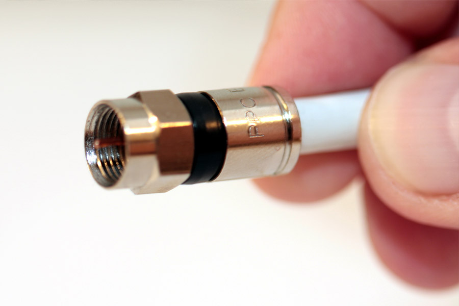
Our digital coaxial cables have many accessories. For more information, don’t hesitate to call us on 0121 508 6890 or get in touch via Contact Page.

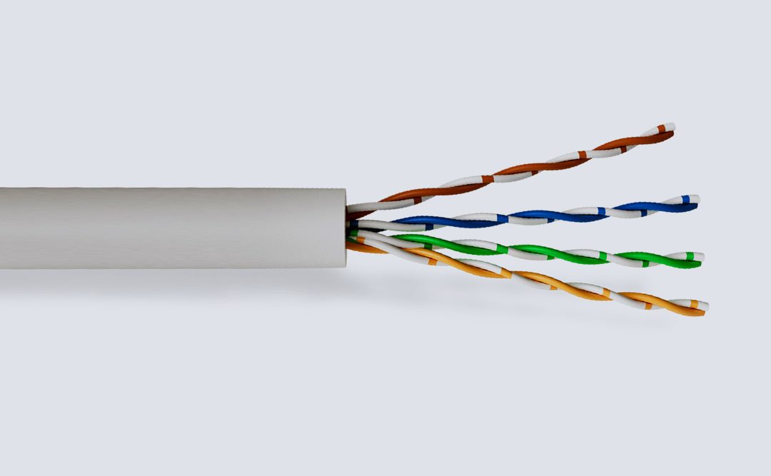
Internal telephone cables.Local Area Network Cable
Posted in Communication, Network Cable Comments Off on Local Area Network Cable AS-I BUS Cable
Posted in Communication, Network Cable, Bus Cable Comments Off on AS-I BUS Cable Profinet Type A Cable
Posted in Communication, Network Cable, Bus Cable Comments Off on Profinet Type A Cable Profibus PA PVC Cable
Posted in Communication, Network Cable, Bus Cable Comments Off on Profibus PA PVC Cable Profibus PA FRNC-LSZH Cable
Posted in Communication, Network Cable, Bus Cable Comments Off on Profibus PA FRNC-LSZH Cable KNX/EIB Cable
Posted in Communication, Network Cable, Bus Cable Comments Off on KNX/EIB Cable Profibus PA LSZH SWB Cable
Posted in Communication, Network Cable, Bus Cable Comments Off on Profibus PA LSZH SWB Cable Profibus DP LSZH SWB Cable
Posted in Communication, Network Cable, Bus Cable Comments Off on Profibus DP LSZH SWB Cable Profinet PUR Cable
Posted in Communication, Network Cable, Bus Cable Comments Off on Profinet PUR Cable CAT 5E
Posted in Local Area Network Cable, Communication Comments Off on CAT 5E Cat 5E 25 Pair U/UTP PE Duct Grade Cable
Posted in Local Area Network Cable, Communication, Network Cable Comments Off on Cat 5E 25 Pair U/UTP PE Duct Grade Cable Cat 5E 25 Pair U/UTP LSZH Cable
Posted in Local Area Network Cable, Communication, Network Cable Comments Off on Cat 5E 25 Pair U/UTP LSZH Cable Cat 5E F/UTP PVC Cable
Posted in Local Area Network Cable, Communication, Network Cable Comments Off on Cat 5E F/UTP PVC Cable Profibus DP FC L2/FIP PVC Cable
Posted in Communication, Network Cable, Bus Cable Comments Off on Profibus DP FC L2/FIP PVC Cable Profibus DP FC L2/FIP LSZH Cable
Posted in Communication, Network Cable, Bus Cable Comments Off on Profibus DP FC L2/FIP LSZH Cable DeviceNet Thick FRNC LSZH Cable
Posted in Communication, Network Cable, Bus Cable Comments Off on DeviceNet Thick FRNC LSZH Cable DeviceNet Thin LSZH Cable
Posted in Communication, Network Cable, Bus Cable Comments Off on DeviceNet Thin LSZH Cable Cat 5E U/UTP PVC Cable
Posted in Local Area Network Cable, Communication, Network Cable Comments Off on Cat 5E U/UTP PVC Cable Cat 5E U/UTP PE External Cable
Posted in Local Area Network Cable, Communication, Network Cable Comments Off on Cat 5E U/UTP PE External Cable Cat 5E F/UTP PE Cable
Posted in Local Area Network Cable, Communication, Network Cable Comments Off on Cat 5E F/UTP PE Cable Cat 5E F/UTP LSZH Cable
Posted in Local Area Network Cable, Communication, Network Cable Comments Off on Cat 5E F/UTP LSZH Cable Cat 5E PE F/UTP GSWB LSZH Cable
Posted in Local Area Network Cable, Communication, Network Cable Comments Off on Cat 5E PE F/UTP GSWB LSZH Cable Cat 5E U/UTP SWA LSZH Cable
Posted in Local Area Network Cable, Communication, Network Cable Comments Off on Cat 5E U/UTP SWA LSZH Cable Cat 5E U/UTP LSZH Cable
Posted in Local Area Network Cable, Communication, Network Cable Comments Off on Cat 5E U/UTP LSZH Cable Cat 6 F/UTP PE Cable
Posted in Local Area Network Cable, Communication, Network Cable Comments Off on Cat 6 F/UTP PE Cable Cat 6 U/UTP PE Cable
Posted in Local Area Network Cable, Communication, Network Cable Comments Off on Cat 6 U/UTP PE Cable Cat 6 U/UTP LSZH Cable
Posted in Local Area Network Cable, Communication, Network Cable Comments Off on Cat 6 U/UTP LSZH Cable Cat 6A U/FTP LSZH Cable
Posted in Local Area Network Cable, Communication, Network Cable Comments Off on Cat 6A U/FTP LSZH Cable Cat 6 F/UTP LSZH Cable
Posted in Local Area Network Cable, Communication, Network Cable Comments Off on Cat 6 F/UTP LSZH Cable Cat 7 S/FTP 4 Pair LSZH Cable
Posted in Local Area Network Cable, Communication, Network Cable Comments Off on Cat 7 S/FTP 4 Pair LSZH Cable
Cable Construction
| Conductor | Solid Copper Conductor |
| Insulation | PE (Polyethylene) |
| Filler | PE (Polyethylene) |
| Bedding | Mylar Shield |
| Rip Cord | Nylon |
| Sheath | PE (Polyethylene) |
Dimensions
| No. of Pairs | Nominal Diameter of Conductor mm | Nominal Thickness of Pair Insulation mm | Nominal Overall Diameter mm | Nominal Weight kg/km |
|---|---|---|---|---|
| 25 | 0.51 | 0.91 | 12 | 154.4 |
| Frequency MHz | Attenuation (-dB/100m)(±30%) | Next Worst Pair (dB/100m) | RL (dB/100m) |
|---|---|---|---|
| 1 | 2 | 52.24 | 16 |
| 4 | 4.1 | 45.04 | 18.4 |
| 8 | 5.8 | 41.44 | 19.6 |
| 10 | 6.5 | 40.24 | 20 |
| 16 | 8.2 | 37.84 | 20 |
| 20 | 9.3 | 36.64 | 20 |
| 25 | 10.4 | 35.44 | 19.44 |
| 31.25 | 11.7 | 34.32 | 18.88 |
| 62.5 | 17 | 30.72 | 17.2 |
| 100 | 22 | 28.24 | 16.08 |
| Impedance (1-100MHz) ohms | Maximum DC Resistance of Conductor At 20ºC ohms/km |
|---|---|
| 100(±15) | 101.2 |
Cable Construction
| Conductor | Class 1 Solid Copper Conductor |
| Insulation | PE (Polyethylene) |
| Filler | PE (Polyethylene) filler core |
| Bedding | Mylar tape |
| Sheath | LSZH (Low Smoke Zero Halogen) |
Dimensions
| No. of Pairs | Nominal Diameter of Conductor mm² | Nominal Thickness of Pair Insulation mm | Nominal Overall Diameter mm | Nominal Weight kg/km |
|---|---|---|---|---|
| 25 | 0.51 | 0.91 | 12 | 194 |
| Frequency MHz | Attenuation at (-dB/100m)(±15%) | Next (dB)Min | RL (dB)(±15%) |
|---|---|---|---|
| 1 | 2 | 65.3 | 20 |
| 4 | 4.1 | 56.3 | 23 |
| 8 | 5.8 | 51.8 | 24.5 |
| 10 | 6.5 | 50.3 | 25 |
| 16 | 8.2 | 47.3 | 25 |
| 20 | 9.3 | 45.8 | 25 |
| 25 | 10.4 | 44.3 | 24.3 |
| 31.25 | 11.7 | 42.9 | 23.6 |
| 62.5 | 17 | 38.4 | 21.5 |
| 100 | 22 | 35.3 | 20.1 |
| Impedance (1-100Hz) ohms | Maximum DC Resistance of Conductor At 20ºC ohms/km |
|---|---|
| 100(±15) | 101.3 |
Cable Construction
| Conductor | Class 1 Solid Copper Conductor |
| Insulation | HDPE (High Density Polyethylene) |
| Screen | Aluminium Foil |
| Drain Wire | Tinned Copper |
| Sheath | PVC (Polyvinyl Chloride) |
Dimensions
| No. of Pairs (24 AWG) | Nominal Diameter Over Insulation mm | Nominal Overall Diameter mm | Nominal Weight kg/305m box |
|---|---|---|---|
| 4 | 1 | 6.2 | 14 |
| Frequency MHz | Attenuation dB/100m | Next dB | PS - Next dB | RL dB | Elfext dB | PS - Elfext dB/100m | Phase Delay ns |
|---|---|---|---|---|---|---|---|
| 1 | 2 | 65.3 | 62.3 | 20 | 63.8 | 60.8 | 570 |
| 4 | 4.1 | 56.3 | 53.3 | 23 | 51.8 | 48.8 | 552 |
| 8 | 5.8 | 51.8 | 48.8 | 24.5 | 45.7 | 42.7 | 546.73 |
| 10 | 6.5 | 50.3 | 47.3 | 25 | 43.8 | 40.8 | 545.38 |
| 16 | 8.2 | 47.2 | 44.4 | 25 | 39.7 | 36.7 | 543 |
| 20 | 9.3 | 45.8 | 42.8 | 25 | 37.8 | 34.8 | 542.05 |
| 25 | 10.4 | 44.3 | 41.3 | 24.3 | 35.8 | 32.8 | 541.2 |
| 31.25 | 11.7 | 42.9 | 39.9 | 23.6 | 33.9 | 30.9 | 540.44 |
| 62.5 | 17 | 38.4 | 35.4 | 21.5 | 27.9 | 24.9 | 538.55 |
| 100 | 22 | 35.3 | 32.3 | 20.1 | 23.8 | 20.8 | 537.6 |
| Impedance (1-100MHz) ohms | Maximum Resistance of Conductor At 20ºC ohms/km | Maximum Resistance Unbalance % max |
|---|---|---|
| 100±15 | 95 | 5 |
Cable Construction
| Conductor | Solid Bare Copper Wire - 22/1AWG |
| Insulation | Foam-Skin Polyethylene |
| Bedding | PET (Polyester Tape) |
| Inner Sheath | PVC (Polyvinyl Chloride) |
| Shield | AL/PET (Aluminium / Polyester Tape) |
| Sheath | PVC (Polyvinyl Chloride) |
| Braid | Tinned Copper Wires, 60% Coverage |
Dimensions
| No. of Pairs | Nominal Cross Sectional Area mm² | Nominal Conductor Diameter mm | Nominal Insulation Diameter mm | Nominal Outer Diameter of Inner Sheath mm | Nominal Diameter of Outer Sheath mm | Nominal Weight kg/km |
|---|---|---|---|---|---|---|
| 1 | 0.35 | 0.64 | 2.5 | 5.5 | 7.9 | 76 |
| Max DC Loop Conductor Resistance Ω/km | Maximum DC Conductor Resistance Ω/km | Capacitance at 800Hz pF/km | Impedance (3÷20MHz) Ω(±10%) | Maximum Attenuation dB/km | |||
|---|---|---|---|---|---|---|---|
| 9.6kHz | 38.4kHz | 4kHz | 16kHz | ||||
| 115 | 57.5 | 29 | 150 | 0.3 | 0.5 | 2.1 | 4 |
| Dielectric Strength kVac / 1 min | Minimum Insulation Resistance GΩ x KM | Maximum Installation Pulling N | |
|---|---|---|---|
| Conductor/Conductor | Conductor/Shield | ||
| 1.5 | 1.5 | 5 | 100 |
Cable Construction
| Conductor | Solid Bare Copper Wire - 22/1AWG |
| Insulation | Foam-Skin Polyethylene |
| Bedding | PET (Polyester Tape) |
| Inner Sheath | Flame Retardant Halogen Free Compound |
| Shield | AL/PET (Aluminium / Polyester Tape) |
| Sheath | FRNC-LSZH (Flame Retardant Non-Corrosive Low Smoke Zero Halogen) Compound |
| Braid | Tinned Copper Wires, 60% Coverage |
Dimensions
| No. of Pairs | Nominal Cross Sectional Area mm² | Nominal Conductor Diameter mm | Nominal Insulation Diameter mm | Nominal Outer Diameter of Inner Sheath mm | Nominal Diameter of Outer Sheath mm | Nominal Weight kg/km |
|---|---|---|---|---|---|---|
| 1 | 0.35 | 0.64 | 2.5 | 5.5 | 7.9 | 76 |
| Max DC Loop Conductor Resistance Ω/km | Maximum DC Conductor Resistance Ω/km | Capacitance at 800Hz pF/km | Impedance (3÷20MHz) Ω(±10%) | Maximum Attenuation dB/km | |||
|---|---|---|---|---|---|---|---|
| 9.6kHz | 38.4kHz | 4kHz | 16kHz | ||||
| 115 | 57.5 | 29 | 150 | 0.3 | 0.5 | 2.1 | 4 |
| Dielectric Strength kVac / 1 min | Minimum Insulation Resistance GΩ x KM | Maximum Installation Pulling N | |
|---|---|---|---|
| Conductor/Conductor | Conductor/Shield | ||
| 1.5 | 1.5 | 5 | 100 |
Cable Construction
| Conductor | Data Pair: Stranded Tinned Copper Wires - 18/19AWG (0.25mm²) Power Supply Pair: Stranded Tinned Copper Wires - 15/19AWG (0.35mm²) |
| Insulation | Data Pair: Foam-Skin Polyethylene Power Supply Pair: Solid Polyethylene |
| Bedding | PET (Polyester Tape) |
| Individual Pair Shield | AL/PET (Aluminium / Polyester Tape) |
| Overall Shield | TCWB (Tinned Copper Wire Braid) |
| Sheath | FRNC-LSZH (Flame Retardant Non-Corrosive Low Smoke Zero Halogen) Compound |
| Drain Wire | Tinned Copper |
Dimensions
| Nominal Cross Sectional Area of Data Pair Conductor mm² | Nominal Cross Sectional Area of Power Supply Pair Conductor mm² | Nominal Coverage of Wire Braid % | Nominal Diameter of Outer Sheath mm | Nominal Weight kg/km |
|---|---|---|---|---|
| 0.93 | 1.93 | 65 | 11.9 | 220 |
| DC Conductor Resistance Ω/km | Capacitance at 800Hz Data Pair pF/km | Impedance ≥ 1MHz Data Pair Ω | Attenuation dB/km | Dielectric Strength kVac/1min | Minimum Insulation Resistance GΩ x km | Transfer Impedance at 10MHz mΩ/m | |||
|---|---|---|---|---|---|---|---|---|---|
| Data | Power Supply Pair | at 125kHz | at 500kHz | at 1MHz | |||||
| 23.2 | 11.3 | 40 | 120 | 0.4 | 0.8 | 1.25 | 2 | 5 | 15 |
Cable Construction
| Conductor | Data Pair: Class 2 Stranded Tinned Copper - 24/19AWG (0.25mm²) Power Pair: Class 2 Stranded Tinned Copper - 22/19AWG (0.35mm²) |
| Insulation | Pair 1 - Data: Foam-Skin PE (Polyethylene) Pair 2 - Power: Solid PE (Polyethylene) |
| Shield | AL/PET (Aluminium / Polyester Tape) |
| Overall Shield | TCWB (Tinned Copper Wire Braid) |
| Sheath | FRNC-LSZH (Flame Retardant Non-Corrosive Low Smoke Zero Halogen) |
| Drain Wire | Tinned Copper - 24AWG |
Dimensions
| Nominal Cross Sectional Area of Data Pair Conductor mm² | Nominal Cross Sectional Area of Power Supply Pair Conductor mm² | Nominal Coverage Metallic Braid % | Nominal Diameter of Outer Sheath mm | Nominal Weight kg/km |
|---|---|---|---|---|
| 0.25 | 0.35 | 65 | 6.9 | 70 |
| DC Conductor Resistance Ω/km | Capacitance at 800Hz Data Pair pF/km | Impedance ≥ 1MHz Data Pair Ω | Attenuation dB/km | Dielectric Strength kVac/1min | Minimum Insulation Resistance GΩ x km | Transfer Impedance at 10MHz mΩ/m | |||
|---|---|---|---|---|---|---|---|---|---|
| Data | Power Supply Pair | at 125kHz | at 500kHz | at 1MHz | |||||
| 77 | 52 | 40 | 120 | 0.9 | 1.6 | 2.1 | 1.5 | 5 | 7 |

Control flex cables are designed to measure, design or regulate in the field of process automation.
There are three different types of Control Cable in the area of process automation: CY, YY and SY Cable.
With its GSWB braid SY is suited to installations with medium to high mechanical stress. YY and CY Control Cable are very similar in construction, but without the mechanical protection provided by the steel wire.
YY is a versatile cable that works well in environments with only light mechanical stress and CY Cable has a tinned copper wire braid and polyester binder tape, which provide protection against external electromagnetic influences.
The page you requested could not be found. Try refining your search, or use the navigation above to locate the post.

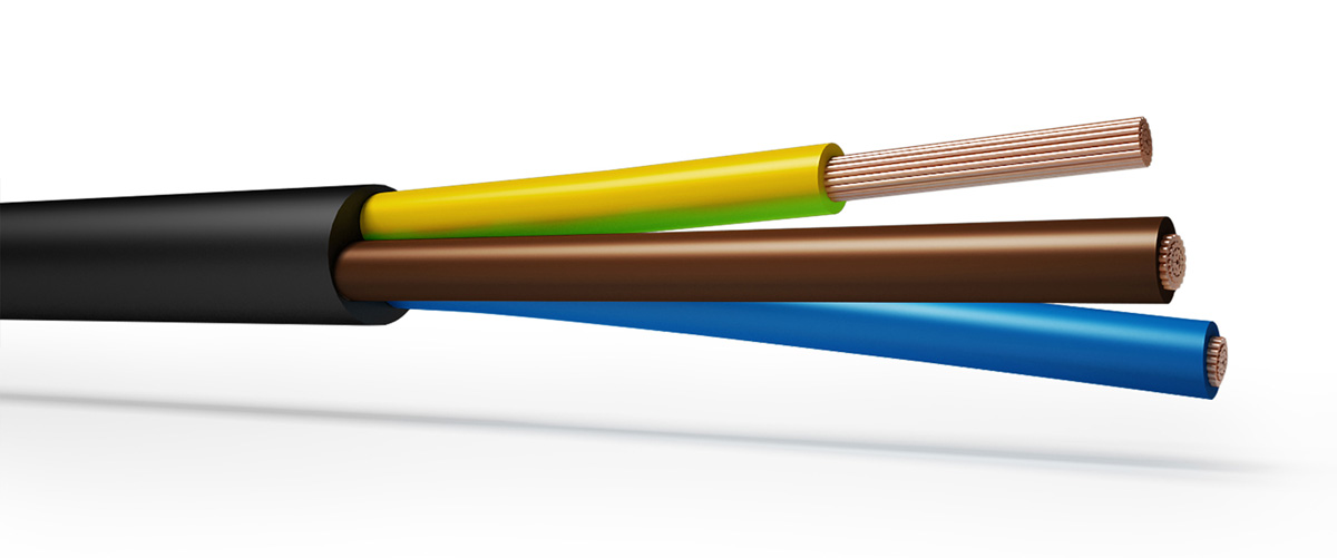
Flexible Rubber cables are robust and massively flexible designed primarily as a trailing cable for use in the supply of power for portable or mobile tools and equipment suitable to operate under light stress in dry or damp conditions.
The page you requested could not be found. Try refining your search, or use the navigation above to locate the post.

Instrumentation and thermocouple cables are designed not only to supply power but to monitor activity within the cable. Instrumentation cables are used to monitor electrical deviation whereas thermocouple cables measure temperature.
The page you requested could not be found. Try refining your search, or use the navigation above to locate the post.


Low Voltage Power Cables, Aluminum and Copper conductors of voltage range:0.6/1.0 kV
Copper Conductor Cables
Aluminium Conductor Cables
Thermoplastic/ PVC Insulated Cables
Thermoset/XLPE Insulated Cables
Armoured/ Non – Armoured Cables
Single core cables up to and including 1000 mm2
2 core cables up to and including 95 mm2
3, 4 core & 4 core with reduced neutral cables up to and including 500 mm2
IEC 60502 (Part 1)”PVC/ XLPE insulated cables” single core /multi-core BS 5467 for XLPE insulated Armoured cables
BS 7889 for XLPE insulated single core unarmoured cables
The page you requested could not be found. Try refining your search, or use the navigation above to locate the post.

Marine, oil and petrochemical cables are designed to withstand the harsh environments associated with offshore power generation.
These cables are built to withstand high and low temperatures, salt water, acid, humidity and mud making them perfect for use aboard ships, on offshore platforms and other oil drilling and production facilities.
The page you requested could not be found. Try refining your search, or use the navigation above to locate the post.

A number of different types of cables are used in mines. There are fixed mining cables and portable mining cables, the latter being described here.
The key requirements of portable cables are flexibility, and resistance to mechanical abrasion and damage. Due to the additional demands put on portable mining cables used for reeling and dereeling applications, special design may be required.
There are many types of portable mining cables. They are available in ratings up to 25 kV, and may have as many as five conductors. An example of SHD-GC Cable, is shown in the illustration. It has three insulated, shielded conductors, two bare ground wires, a ground check wire, and an overall jacket. The conductors for this cable are annealed, bare or tinned copper wires. The braided shield may be tin-coated wires, or a tin-coated copper wire/textile composite.
The grounding conductor(s) annealed, bare or tinned, stranded copper wires, and the ground check conductor is annealed, bare, stranded copper wires with EPR insulation and nylon braid, elastomeric jacket holds the conductor assembly firmly in place, to minimize snaking and cork-screwing during reeling and dereeling.
Cables Britain offer a wide range of Network Rail style cables to be used in the railway and highway industry. Our cables have been designed, tested and approved to meet the specific standards of their respective industries.
The page you requested could not be found. Try refining your search, or use the navigation above to locate the post.
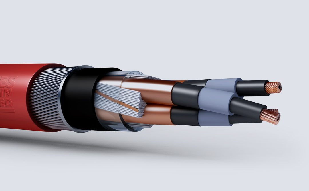
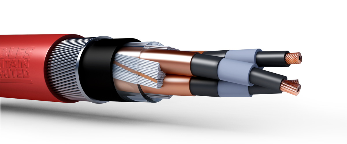
Medium power cables have voltage grade greater than 1 kV. Medium voltage usually goes up to 46 kV.
Medium Voltage distribution systems begin at substations and supply electricity to a wide spectrum of power consumers. When selecting a cable, the basic aim is to safely provide adequate electrical power, with continuous, trouble-free operation, in a system that is able to withstand unexpected demands and overload conditions. Each installation has particular requirements that must be considered. There are distinct benefits from specifying a copper-conductor cable that has been manufactured under rigid specification and quality control procedures. It will provide maximum performance with minimum maintenance. There are seven types different by construction for medium voltage copper power cables in the 1 kV to 46 kV range. Most are available in single- and multi-core configurations. There are ranges of sizes and design variations for each type.
The page you requested could not be found. Try refining your search, or use the navigation above to locate the post.

For more information, don’t hesitate to call us on 0121 508 6890 or get in touch via our Contact Page.


| Conductor | Class 5 tinned conductor |
| Insulation | EPR (Ethylene Propylene Rubber) Type GP4 according to BS 7655 |
| Screen (C3 only) | AL (Aluminium Tape) |
| Drain Wire | Type C3 only |
| Sheath | HDPCP (Heavy Duty Polychloroprene) Type RS2 according to BS 7655 |
| Bedding | PET (Polyethylene Terephthalate) |
Dimensions
| Cable Type | No. of Cores | Nominal Cross Sectional Area mm² | Minimum Thickness of Sheath mm | Minimum Overall Diameter mm | Maximum Overall Diameter mm | Nominal Weight kg/km |
|---|---|---|---|---|---|---|
| C1 | 1 | 2.5 | 3.8 | 11.2 | 14 | 174 |
| C2 | 2 | 2.5 | 3.8 | 14.9 | 18.8 | 338 |
| C2 | 4 | 2.5 | 3.8 | 16.4 | 20.9 | 450 |
| C2 | 7 | 2.5 | 3.8 | 18.7 | 23.7 | 612 |
| C2 | 10 | 2.5 | 3.8 | 22.5 | 28.6 | 836 |
| C2 | 6 x 2 | 0.75 | 3.8 | 23.2 | 29.3 | 868 |
| C2 | 12 | 2.5 | 3.8 | 23.2 | 29.3 | 909 |
| C2 | 16 | 2.5 | 3.8 | 25.3 | 32 | 985 |
| C3 | 2+ Drain | 2.5 | 3.8 | 15 | 20 | 341 |
| Nominal Cross Sectional Area mm² | Maximum Diameter of Wires in Conductor mm | Maximum Resistance of Conductor At 20ºC |
|---|---|---|
| Metal-Coated Wires ohms/km | ||
| 0.75 | 0.4 | 26.7 |
| 2.5 | 0.26 | 8.21 |
For more information, don’t hesitate to call us on 0121 508 6890 or get in touch via our Contact Page.
| Conductor | Class 2 stranded tinned conductor |
| Insulation | EPR (Ethylene Propylene Rubber) Type GP4 according to BS 7655 |
| Sheath | HDPCP (Heavy Duty Polychloroprene) Type RS2 according to BS 7655 |
Dimensions
| Cable Type | No. of Cores | Nominal Cross Sectional Area mm² | Minimum Thickness of Sheath mm | Minimum Overall Diameter mm | Maximum Overall Diameter mm | Nominal Weight kg/km |
|---|---|---|---|---|---|---|
| B1 | 1 | 2.5 | 2 | 7.2 | 8.9 | 34 |
| B1 | 1 | 10 | 2 | 9.4 | 11.8 | 205 |
| B1 | 1 | 35 | 2 | 12.9 | 16.1 | 495 |
| B2 | 2 | 1 | 2 | 9.9 | 13 | 240 |
| B2 | 2 | 1.5 | 2 | 9.4 | 12.1 | 151 |
| B2 | 2 | 2.5 | 2 | 10.5 | 13.1 | 187 |
| B2 | 2 | 4 | 2 | 13.2 | 16.3 | 267 |
| B2 | 2 | 10 | 2 | 15 | 18.7 | 448 |
| B2 | 2 | 16 | 2 | 16.7 | 20.9 | 630 |
| B2 | 2 | 35 | 2.2 | 22.3 | 27.8 | 1520 |
| B2 | 2 | 70 | 2.4 | 28.8 | 36 | 1904 |
| B2 | 2 | 95 | 2.6 | 33.2 | 41.5 | 2885 |
| B2 | 3 | 10 | 2 | 17.3 | 20.7 | 525 |
| B2 | 3 | 16 | 2 | 19.8 | 23.2 | 770 |
| B2 | 4 | 0.75 | 2 | 10.2 | 12.8 | 173 |
| B2 | 4 | 1.5 | 2 | 10.9 | 13.7 | 220 |
| B2 | 4 | 2.5 | 2 | 11.9 | 14.8 | 264 |
| B2 | 7 | 0.75 | 2 | 11.8 | 14.7 | 240 |
| B2 | 7 | 1.5 | 2 | 12.6 | 15.8 | 305 |
| B2 | 7 | 2.5 | 2 | 13.8 | 17.2 | 390 |
| B2 | 10 | 0.75 | 2 | 14.4 | 18 | 345 |
| B2 | 10 | 1.5 | 2 | 15.6 | 19.4 | 405 |
| B2 | 10 | 2.5 | 2 | 17.1 | 21.3 | 565 |
| B2 | 12 | 0.75 | 2 | 14.8 | 18.5 | 350 |
| B2 | 12 | 1.5 | 2 | 16 | 20 | 465 |
| B2 | 12 | 2.5 | 2 | 17.6 | 22 | 570 |
| B2 | 19 | 0.75 | 2 | 17 | 21.3 | 490 |
| B2 | 19 | 1.5 | 2 | 18.5 | 23.1 | 649 |
| B2 | 19 | 2.5 | 2 | 20.4 | 25.5 | 886 |
| B2 | 27 | 0.75 | 2 | 20.1 | 25.1 | 640 |
| B2 | 27 | 1.5 | 2.2 | 22.2 | 27.8 | 880 |
| B2 | 27 | 2.5 | 2.2 | 24.6 | 30.7 | 1225 |
| B2 | 37 | 0.75 | 2.2 | 22.7 | 28.4 | 850 |
| B2 | 37 | 1.5 | 2.2 | 25.1 | 31.4 | 1190 |
| B2 | 37 | 2.5 | 2.4 | 27.8 | 34.7 | 1190 |
| B2 | 48 | 0.75 | 2.2 | 25.7 | 32.2 | 1650 |
| B2 | 48 | 1.5 | 2.4 | 28.1 | 35.1 | 1590 |
| B2 | 48 | 2.5 | 2.6 | 31.2 | 39 | 1980 |
| B2 | 6 x 2 | 0.75 | 2 | 19.7 | 24.6 | 465 |
| B2 | 6 x 2 | 2.5 | 2 | 23.7 | 29.6 | 570 |
| Nominal Cross Sectional Area mm² | Maximum No. Of Wires In Conductor | Maximum Resistance of Conductor At 20ºC | |||||
|---|---|---|---|---|---|---|---|
| Circular | Circular Compacted | Shaped | Annealed Copper Conductor | ||||
| Cu | Al | Cu | Al | Cu | Al | Metal-Coated Wires ohms/km | |
| 0.75 | 7 | - | - | - | - | - | 24.8 |
| 1 | 7 | - | - | - | - | - | 18.2 |
| 1.5 | 7 | - | 6 | - | - | - | 12.2 |
| 2.5 | 7 | - | 6 | - | - | - | 7.56 |
| 4 | 7 | - | 6 | - | - | - | 4.7 |
| 6 | 7 | - | 6 | - | - | - | 3.11 |
| 10 | 7 | 7 | 6 | 6 | - | - | 1.84 |
| 16 | 7 | 7 | 6 | 6 | - | - | 1.16 |
| 35 | 7 | 7 | 6 | 6 | 6 | 6 | 0.529 |
| 70 | 19 | 19 | 12 | 12 | 12 | 12 | 0.27 |
| 95 | 19 | 19 | 15 | 15 | 15 | 15 | 0.195 |
For more information, don’t hesitate to call us on 0121 508 6890 or get in touch via our Contact Page.


The idea of an electronic sensor cable had been developed as early as 1983. We are in service for the safety of individuals, commodities, and real estate. Concentration on early fire detection in tunnels with the LIST system (sec20) had been the main focus for several years.
The d-LIST system (sec15) was developed in1999 to gain more market share in industrial facilities. In 2001, the LIST system gained strong attention in large tunnel systems, which made us the leader in unit and sensor cable redundancy up until today (LIST RDT-mode, Rerouted Data Transmission).
The line-type heat detector LIST is VdS-approved according to EN 54-22, response class A1N and A2N, environmental group III (G 213072), as well as certified according to ATEX zones 2 and 22.
The line-type heat detector d-LIST is VdS-approved according to EN 54-5, response class A1 (G205143), as well as certified according to ATEX zones 2 and 22, and according to DNV-GL (60 380 – 09 HH).
The system interrogates both actual temperature and rate of rise.
Project inquiries are processed according to customer specifications, in order to offer the optimum solution. You will be supported by a competent team with 25 years of know-how in all matters concerning line-type heat detectors.
Our safety relevant systems will be commissioned and maintained on a yearly basis by skilled and qualified personnel.
Play safe by getting expert advice. Application Engineering and System Design is conducted with rigid adherence to client specifications. In addition, CBL’s engineers utilise BS5839 as the basis of all our designs.
It is CBL’s desire to work with the complete chain of stake holders within the fire detection market place. To this aim we offer: CPD content seminars – to show and explain our systems.
To utilise the unique in house software and the full package of Commissioning, Installation, Maintenance and Service. It is our intention to Supply and design only, with the Fire Specialists engaging their clients in the way they do best! If required we could assist with commissioning of your first order.
CBL’s sales team will discuss the product and product design with: the End Client, Consultant, Insurer, Mechanical and Electrical Contractor and fire specialist to ensure the project is completed with safety in mind!
| Conductor | 1.0mm² to 1.5mm²: Class 5 tinned copper conductor according to BS EN 60228 (previously BS 6360) 2.5mm² and above: Class 2 tinned copper conductor according to BS EN 60228 (previously BS 6360) |
| Insulation | Halogen free elastomer EPR Type GP4 according to BS 7655 |
| Inner Sheath | HOFR (Heat and Oil Resistant and Flame Retardant), halogen-free elastomer Type SW4 according to BS 7655 |
| Armour | Galvanized steel wire braid* |
| Outer Sheath | HOFR (Heat and Oil Resistant and Flame Retardant), halogen-free elastomer Type SW4 according to BS 7655 |
| Bedding | Suitable tape between the braid and outer sheath |
| Note | * Tinned copper wire braid version available on request |
Dimensions
| No. of Cores | Conductor Class | Nominal Cross Sectional Area mm² | Nominal Thickness of Insulation mm | Nominal Thickness of Inner Sheath mm | Nominal Diameter of Steel Wires in Braid mm | Nominal Thickness of Outer Sheath mm | Nominal Overall Diameter mm | Nominal Weight kg/km |
|---|---|---|---|---|---|---|---|---|
| 2 | 5 | 1 | 0.8 | 1 | 0.3 | 1.2 | 11.6 | 200 |
| 2 | 5 | 1.5 | 0.8 | 1.1 | 0.3 | 1.2 | 12.4 | 241 |
| 2 | 2 | 2.5 | 0.8 | 1.1 | 0.3 | 1.2 | 13.4 | 283 |
| 2 | 2 | 4 | 1 | 1.2 | 0.3 | 1.3 | 15.6 | 387 |
| 2 | 2 | 6 | 1 | 1.2 | 0.3 | 1.4 | 16.9 | 476 |
| 2 | 2 | 10 | 1 | 1.3 | 0.3 | 1.4 | 19.2 | 627 |
| 2 | 2 | 16 | 1 | 1.4 | 0.3 | 1.5 | 22 | 853 |
| 2 | 2 | 25 | 1.2 | 1.5 | 0.3 | 1.7 | 26.1 | 1212 |
| 2 | 2 | 35 | 1.2 | 1.6 | 0.3 | 1.8 | 28.8 | 1532 |
| 2 | 2 | 50 | 1.4 | 1.7 | 0.45 | 2 | 33 | 2038 |
| 2 | 2 | 70 | 1.4 | 1.9 | 0.45 | 2.1 | 37.1 | 2680 |
| 2 | 2 | 95 | 1.6 | 2.1 | 0.45 | 2.3 | 42.2 | 3593 |
| 2 | 2 | 120 | 1.6 | 2.2 | 0.45 | 2.5 | 46.2 | 4291 |
| 2 | 2 | 150 | 1.8 | 2.3 | 0.45 | 2.6 | 50.5 | 5120 |
| 2 | 2 | 185 | 2 | 2.5 | 0.45 | 2.8 | 55.7 | 6404 |
| 2 | 2 | 240 | 2.2 | 2.8 | 0.45 | 3.1 | 62.8 | 8210 |
| 2 | 2 | 300 | 2.4 | 3 | 0.45 | 3.3 | 69.1 | 10016 |
| 3 | 5 | 1 | 0.8 | 1.1 | 0.3 | 1.2 | 12.2 | 237 |
| 3 | 5 | 1.5 | 0.8 | 1.1 | 0.3 | 1.2 | 12.9 | 263 |
| 3 | 2 | 2.5 | 0.8 | 1.1 | 0.3 | 1.3 | 14.1 | 323 |
| 3 | 2 | 4 | 1 | 1.2 | 0.3 | 1.3 | 16.3 | 439 |
| 3 | 2 | 6 | 1 | 1.2 | 0.3 | 1.4 | 17.7 | 547 |
| 3 | 2 | 10 | 1 | 1.3 | 0.3 | 1.5 | 20.4 | 743 |
| 3 | 2 | 16 | 1 | 1.4 | 0.3 | 1.6 | 23.3 | 1029 |
| 3 | 2 | 25 | 1.2 | 1.6 | 0.3 | 1.8 | 27.8 | 1515 |
| 3 | 2 | 35 | 1.2 | 1.7 | 0.45 | 1.9 | 31.4 | 2032 |
| 3 | 2 | 50 | 1.4 | 1.8 | 0.45 | 2 | 35 | 2547 |
| 3 | 2 | 70 | 1.4 | 2 | 0.45 | 2.2 | 39.6 | 3340 |
| 3 | 2 | 95 | 1.6 | 2.2 | 0.45 | 2.4 | 45.5 | 4514 |
| 3 | 2 | 120 | 1.6 | 2.3 | 0.45 | 2.6 | 49.3 | 5408 |
| 3 | 2 | 150 | 1.8 | 2.5 | 0.45 | 2.8 | 54.3 | 6587 |
| 3 | 2 | 185 | 2 | 2.7 | 0.45 | 3 | 59.9 | 8197 |
| 3 | 2 | 240 | 2.2 | 2.9 | 0.45 | 3.2 | 67 | 10475 |
| 3 | 2 | 300 | 2.4 | 3.2 | 0.45 | 3.5 | 74.1 | 12878 |
| 4 | 5 | 1 | 0.8 | 1.1 | 0.3 | 1.2 | 12.9 | 262 |
| 4 | 5 | 1.5 | 0.8 | 1.1 | 0.3 | 1.3 | 13.9 | 301 |
| 4 | 2 | 2.5 | 0.8 | 1.1 | 0.3 | 1.3 | 15.1 | 384 |
| 4 | 2 | 4 | 1 | 1.2 | 0.3 | 1.4 | 17.7 | 532 |
| 4 | 2 | 6 | 1 | 1.3 | 0.3 | 1.5 | 19.4 | 673 |
| 4 | 2 | 10 | 1 | 1.4 | 0.3 | 1.6 | 22.3 | 917 |
| 4 | 2 | 16 | 1 | 1.5 | 0.3 | 1.7 | 25.6 | 1287 |
| 4 | 2 | 25 | 1.2 | 1.7 | 0.45 | 1.9 | 31.3 | 1999 |
| 4 | 2 | 35 | 1.2 | 1.8 | 0.45 | 2 | 34.2 | 2525 |
| 4 | 2 | 50 | 1.4 | 1.9 | 0.45 | 2.2 | 38.7 | 3159 |
| 4 | 2 | 70 | 1.4 | 2.1 | 0.45 | 2.4 | 43.7 | 4226 |
| 4 | 2 | 95 | 1.6 | 2.3 | 0.45 | 2.6 | 50.2 | 5718 |
| 4 | 2 | 120 | 1.6 | 2.5 | 0.45 | 2.8 | 54.6 | 6876 |
| 4 | 2 | 150 | 1.8 | 2.7 | 0.45 | 3 | 60.1 | 8357 |
| 4 | 2 | 185 | 2 | 2.9 | 0.45 | 3.2 | 66.3 | 10406 |
| 4 | 2 | 240 | 2.2 | 3.2 | 0.45 | 3.5 | 74.6 | 13363 |
| 4 | 2 | 300 | 2.4 | 3.5 | 0.45 | 3.8 | 82.4 | 16433 |
| 5 | 5 | 1.5 | 0.8 | 1.1 | 0.3 | 1.3 | 14.8 | 351 |
| 5 | 2 | 2.5 | 0.8 | 1.2 | 0.3 | 1.3 | 16.3 | 441 |
| 7 | 5 | 1.5 | 0.8 | 1.2 | 0.3 | 1.3 | 16.8 | 452 |
| 7 | 2 | 2.5 | 0.8 | 1.2 | 0.3 | 1.4 | 18.6 | 577 |
| 12 | 5 | 1.5 | 0.8 | 1.3 | 0.3 | 1.5 | 20.1 | 621 |
| 12 | 2 | 2.5 | 0.8 | 1.4 | 0.3 | 1.6 | 22.6 | 836 |
| 19 | 5 | 1.5 | 0.8 | 1.4 | 0.3 | 1.6 | 24.1 | 888 |
| 19 | 2 | 2.5 | 0.8 | 1.5 | 0.3 | 1.7 | 27.1 | 1202 |
| 27 | 5 | 1.5 | 0.8 | 1.6 | 0.3 | 1.8 | 27.5 | 1162 |
| 27 | 2 | 2.5 | 0.8 | 1.7 | 0.45 | 1.9 | 31.4 | 1714 |
| 37* | 5 | 1.5 | 0.8 | 1.7 | 0.45 | 1.9 | 32.1 | 1608 |
Class 2 Stranded Conductors for Single Core and Multi-Core Cables
| Nominal Cross Sectional Area mm² | Minimum No. Of Wires In Conductor | Maximum Resistance of Conductor At 20ºC |
|---|---|---|
| Circular | Annealed Copper Conductor | |
| Cu | Metal-Coated Wires ohms/km | |
| 2.5 | 7 | 7.56 |
| 4 | 7 | 4.7 |
| 6 | 7 | 3.11 |
| 10 | 7 | 1.84 |
| 16 | 7 | 1.16 |
| 25 | 7 | 0.734 |
| 35 | 7 | 0.529 |
| 50 | 19 | 0.391 |
| 70 | 19 | 0.27 |
| 95 | 19 | 0.195 |
| 120 | 37 | 0.154 |
| 150 | 37 | 0.126 |
| 185 | 37 | 0.1 |
| 240 | 37 | 0.0762 |
| 300 | 61 | 0.0607 |
| Nominal Cross Sectional Area mm² | Maximum Diameter of Wires in Conductor mm | Maximum Resistance of Conductor at 20°C | |
|---|---|---|---|
| Plain Wires ohms/km | Metal-Coated Wires ohms/km | ||
| 1 | 0.21 | 19.5 | 20 |
| 1.5 | 0.26 | 13.3 | 13.7 |
| Nominal Cross Sectional Area mm² | Single Core Amps | 2 Core Amps | 3 and 4 Core Amps | 5 Core Amps | 7 Core Amps | 10 Core Amps | 12 Core Amps | 16 Core Amps | 19 Core Amps | 20 Core Amps | 24 Core Amps | 27 Core Amps | 30 Core Amps | 37 Core Amps |
|---|---|---|---|---|---|---|---|---|---|---|---|---|---|---|
| 1 | 18 | 15 | 13 | 10.5 | 9 | 8 | 8 | 7 | 7 | 7 | 6 | 6 | 6 | 5 |
| 1.5 | 23 | 20 | 16 | 12 | 10 | 9 | 9 | 8 | 7 | 7 | 6.5 | 6.5 | 6 | 6 |
| 2.5 | 30 | 26 | 21 | 16 | 15 | 13 | 12 | 11 | 10 | 10 | 9.5 | 9 | 9 | 8 |
| 4 | 40 | 34 | 28 | - | - | - | - | - | - | - | - | - | - | - |
| 6 | 52 | 44 | 36 | - | - | - | - | - | - | - | - | - | - | - |
| 10 | 72 | 61 | 50 | - | - | - | - | - | - | - | - | - | - | - |
| 16 | 96 | 82 | 67 | - | - | - | - | - | - | - | - | - | - | - |
| 25 | 127 | 108 | 89 | - | - | - | - | - | - | - | - | - | - | - |
| 35 | 157 | 133 | 110 | - | - | - | - | - | - | - | - | - | - | - |
| 50 | 196 | 167 | 137 | - | - | - | - | - | - | - | - | - | - | - |
| 70 | 242 | 206 | 169 | - | - | - | - | - | - | - | - | - | - | - |
| 95 | 293 | 249 | 205 | - | - | - | - | - | - | - | - | - | - | - |
| 120 | 339 | 288 | 237 | - | - | - | - | - | - | - | - | - | - | - |
| 150 | 389 | 331 | 272 | - | - | - | - | - | - | - | - | - | - | - |
| 185 | 444 | 377 | 311 | - | - | - | - | - | - | - | - | - | - | - |
| 240 | 522 | 444 | 365 | - | - | - | - | - | - | - | - | - | - | - |
| 300 | 601 | 511 | 421 | - | - | - | - | - | - | - | - | - | - | - |
De-Rating Factors
| Ambient Temperature °C | 35 | 40 | 45 | 50 | 55 | 60 | 65 | 70 | 75 | 80 |
| DE-RATING FACTOR | 1.1 | 1.05 | 1 | 0.94 | 0.88 | 0.82 | 0.74 | 0.67 | 0.58 | 0.47 |
For more information, don’t hesitate to call us on 0121 508 6890 or get in touch via our Contact Page.
| Conductor | 1mm² to 1.5mm²: Class 5 tinned copper conductor according to BS EN 60228 (previously 6360) 2.5mm² and above: Class 2 tinned copper conductor according to BS EN 60228 (previously 6360) |
| Insulation | Halogen free elastomer compound EPR Type GP4 according to BS 7655 |
| Sheath | HOFR (Heat and Oil Resistant and Flame Retardant), halogen free elastomer compound Type SW4 according to BS 7655 |
Dimensions
| No. of Cores | Conductor Class | Nominal Cross Sectional Area mm² | Nominal Thickness of Insulation mm | Nominal Thickness of Outer Sheath mm | Nominal Overall Diameter mm | Nominal Weight kg/km |
|---|---|---|---|---|---|---|
| 1 | 5 | 1 | 0.8 | 1 | 4.8 | 34 |
| 1 | 5 | 1.5 | 0.8 | 1 | 5.1 | 40 |
| 1 | 2 | 2.5 | 0.8 | 1 | 5.6 | 54 |
| 1 | 2 | 4 | 1 | 1 | 6.5 | 78 |
| 1 | 2 | 6 | 1 | 1 | 7.1 | 101 |
| 1 | 2 | 10 | 1 | 1 | 8.1 | 144 |
| 1 | 2 | 16 | 1 | 1.1 | 9.5 | 216 |
| 1 | 2 | 25 | 1.2 | 1.2 | 11.4 | 328 |
| 1 | 2 | 35 | 1.2 | 1.2 | 12.6 | 429 |
| 1 | 2 | 50 | 1.4 | 1.3 | 14.3 | 551 |
| 1 | 2 | 70 | 1.4 | 1.3 | 16 | 753 |
| 1 | 2 | 95 | 1.6 | 1.4 | 18.6 | 1049 |
| 1 | 2 | 120 | 1.6 | 1.5 | 20.3 | 1274 |
| 1 | 2 | 150 | 1.8 | 1.6 | 22.4 | 1568 |
| 1 | 2 | 185 | 2 | 1.7 | 24.9 | 1949 |
| 1 | 2 | 240 | 2.2 | 1.8 | 28 | 2530 |
| 1 | 2 | 300 | 2.4 | 1.9 | 30.9 | 3134 |
| 1 | 2 | 400 | 2.6 | 2 | 35.3 | 4258 |
| 1 | 2 | 500 | 2.8 | 2.2 | 39.3 | 5337 |
| 2 | 5 | 1 | 0.8 | 1 | 8.1 | 86 |
| 2 | 5 | 1.5 | 0.8 | 1.1 | 8.5 | 103 |
| 2 | 2 | 2.5 | 0.8 | 1.1 | 9.5 | 140 |
| 2 | 2 | 4 | 1 | 1.2 | 11.6 | 210 |
| 2 | 2 | 6 | 1 | 1.2 | 12.7 | 270 |
| 2 | 2 | 10 | 1 | 1.3 | 14.9 | 391 |
| 2 | 2 | 16 | 1 | 1.4 | 17.5 | 574 |
| 2 | 2 | 25 | 1.2 | 1.5 | 21.2 | 864 |
| 2 | 2 | 35 | 1.2 | 1.6 | 23.7 | 1129 |
| 2 | 2 | 50 | 1.4 | 1.7 | 26.9 | 1452 |
| 2 | 2 | 70 | 1.4 | 1.9 | 30.8 | 1991 |
| 2 | 2 | 95 | 1.6 | 2.1 | 35.9 | 2766 |
| 2 | 2 | 120 | 1.6 | 2.2 | 39.1 | 3338 |
| 2 | 2 | 150 | 1.8 | 2.3 | 43.2 | 4097 |
| 3 | 5 | 1 | 0.8 | 1.1 | 8.4 | 100 |
| 3 | 5 | 1.5 | 0.8 | 1.1 | 9 | 122 |
| 3 | 2 | 2.5 | 0.8 | 1.1 | 10.1 | 169 |
| 3 | 2 | 4 | 1 | 1.2 | 12.3 | 257 |
| 3 | 2 | 6 | 1 | 1.2 | 13.5 | 335 |
| 3 | 2 | 10 | 1 | 1.3 | 15.9 | 490 |
| 3 | 2 | 16 | 1 | 1.4 | 18.6 | 732 |
| 3 | 2 | 25 | 1.2 | 1.6 | 22.7 | 1121 |
| 3 | 2 | 35 | 1.2 | 1.7 | 25.4 | 1474 |
| 3 | 2 | 50 | 1.4 | 1.8 | 28.9 | 1893 |
| 3 | 2 | 70 | 1.4 | 2 | 33 | 2611 |
| 3 | 2 | 95 | .6 | 2.2 | 38.5 | 3638 |
| 3 | 2 | 120 | 1.6 | 2.3 | 41.9 | 4400 |
| 3 | 2 | 150 | 1.8 | 2.5 | 46.5 | 5425 |
| 3 | 2 | 185 | 2 | 2.7 | 51.8 | 6754 |
| 3 | 2 | 240 | 2.2 | 2.9 | 58.6 | 8770 |
| 4 | 5 | 1 | 0.8 | 1.1 | 9.1 | 122 |
| 4 | 5 | 1.5 | 0.8 | 1.1 | 9.8 | 149 |
| 4 | 2 | 2.5 | 0.8 | 1.1 | 11 | 210 |
| 4 | 2 | 4 | 1 | 1.2 | 13.4 | 321 |
| 4 | 2 | 6 | 1 | 1.3 | 15 | 428 |
| 4 | 2 | 10 | 1 | 1.4 | 17.6 | 627 |
| 4 | 2 | 16 | 1 | 1.5 | 20.7 | 940 |
| 4 | 2 | 25 | 1.2 | 1.7 | 25.3 | 1442 |
| 4 | 2 | 35 | 1.2 | 1.8 | 28.3 | 1899 |
| 4 | 2 | 50 | 1.4 | 1.9 | 32.1 | 2439 |
| 4 | 2 | 70 | 1.4 | 2.1 | 36.7 | 3370 |
| 4 | 2 | 95 | 1.6 | 2.3 | 42.8 | 4700 |
| 4 | 2 | 120 | 1.6 | 2.5 | 46.8 | 5710 |
| 4 | 2 | 150 | 1.8 | 2.7 | 51.9 | 7035 |
| 5 | 5 | 1.5 | 0.8 | 1.1 | 10.7 | 180 |
| 5 | 2 | 2.5 | 0.8 | 1.2 | 12.2 | 260 |
| 5 | 2 | 4 | 1 | 1.3 | 15.2 | 394 |
| 5 | 2 | 6 | 1 | 1.4 | 16.9 | 463 |
| 5 | 2 | 10 | 1 | 1.5 | 19.6 | 685 |
| 7 | 5 | 1.5 | 0.8 | 1.2 | 12.8 | 252 |
| 7 | 2 | 2.5 | 0.8 | 1.2 | 14.4 | 359 |
| 12 | 5 | 1.5 | 0.8 | 1.3 | 15.6 | 370 |
| 12 | 2 | 2.5 | 0.8 | 1.4 | 17.9 | 543 |
| 19 | 5 | 1.5 | 0.8 | 1.4 | 19.4 | 570 |
| 19 | 2 | 2.5 | 0.8 | 1.5 | 22.2 | 842 |
| 27 | 5 | 1.5 | 0.8 | 1.6 | 22.4 | 766 |
| 37 | 5 | 1.5 | 0.8 | 1.7 | 26.2 | 1037 |
| Nominal Cross Sectional Area mm² | Maximum Diameter of Wires in Conductor mm | Maximum Resistance of Conductor at 20°C | |
|---|---|---|---|
| Plain Wires ohms/km | Metal-Coated Wires ohms/km | ||
| 1 | 0.21 | 19.5 | 20 |
| 1.5 | 0.26 | 13.3 | 13.7 |
| Nominal Cross Sectional Area mm² | Minimum No. Of Wires In Conductor | Maximum Resistance of Conductor At 20ºC | |||||
|---|---|---|---|---|---|---|---|
| Circular | Circular Compacted | Shaped | Annealed Copper Conductor | ||||
| Cu | Al | Cu | Al | Cu | Al | Metal-Coated Wires ohms/km | |
| 2.5 | 7 | - | 6 | - | - | - | 7.56 |
| 4 | 7 | - | 6 | - | - | - | 4.7 |
| 6 | 7 | - | 6 | - | - | - | 3.11 |
| 10 | 7 | 7 | 6 | 6 | - | - | 1.84 |
| 16 | 7 | 7 | 6 | 6 | - | - | 1.16 |
| 25 | 7 | 7 | 6 | 6 | 6 | 6 | 0.734 |
| 35 | 7 | 7 | 6 | 6 | 6 | 6 | 0.529 |
| 50 | 19 | 19 | 6 | 6 | 6 | 6 | 0.391 |
| 70 | 19 | 19 | 12 | 12 | 12 | 12 | 0.27 |
| 95 | 19 | 19 | 15 | 15 | 15 | 15 | 0.195 |
| 120 | 37 | 37 | 18 | 15 | 18 | 15 | 0.154 |
| 150 | 37 | 37 | 18 | 15 | 18 | 15 | 0.126 |
| 185 | 37 | 37 | 30 | 30 | 30 | 30 | 0.1 |
| 240 | 37 | 37 | 34 | 30 | 34 | 30 | 0.0762 |
| 300 | 61 | 61 | 34 | 30 | 34 | 30 | 0.0607 |
| 400 | 61 | 61 | 53 | 53 | 53 | 53 | 0.0475 |
| 500 | 61 | 61 | 53 | 53 | 53 | 53 | 0.0369 |
| Nominal Cross Sectional Area mm² | Single Core Amps | 2 Core Amps | 3 and 4 Core Amps | 5 Core Amps | 7 Core Amps | 12 Core Amps | 19 Core Amps | 27 Core Amps | 37 Core Amps |
|---|---|---|---|---|---|---|---|---|---|
| 1 | 18 | 15 | 13 | 10.5 | - | - | - | - | - |
| 1.5 | 23 | 20 | 16 | 12 | 10 | 9 | 7 | 6.5 | 6 |
| 2.5 | 30 | 26 | 21 | 16 | 15 | 12 | 10 | 9 | 8 |
| 4 | 40 | 34 | 28 | - | - | - | - | - | - |
| 6 | 52 | 44 | 36 | - | - | - | - | - | - |
| 10 | 72 | 61 | 50 | - | - | - | - | - | - |
| 16 | 96 | 82 | 67 | - | - | - | - | - | - |
| 25 | 127 | 108 | 89 | - | - | - | - | - | - |
| 35 | 157 | 133 | 110 | - | - | - | - | - | - |
| 50 | 196 | 167 | 137 | - | - | - | - | - | - |
| 70 | 242 | 206 | 169 | - | - | - | - | - | - |
| 95 | 293 | 249 | 205 | - | - | - | - | - | - |
| 120 | 339 | 288 | 237 | - | - | - | - | - | - |
| 150 | 389 | 331 | 272 | - | - | - | - | - | - |
| 185 | 444 | 377 | 311 | - | - | - | - | - | - |
| 240 | 522 | 444 | 365 | - | - | - | - | - | - |
| 300 | 601 | 511 | 421 | - | - | - | - | - | - |
| 400 | 719 | 611 | 503 | - | - | - | - | - | - |
| 500 | 827 | 703 | 579 | - | - | - | - | - | - |
De-Rating Factors
| Ambient Temperature °C | 35 | 40 | 45 | 50 | 55 | 60 | 65 | 70 | 75 | 80 |
| DE-RATING FACTOR | 1.1 | 1.05 | 1 | 0.94 | 0.88 | 0.82 | 0.74 | 0.67 | 0.58 | 0.47 |
For more information, don’t hesitate to call us on 0121 508 6890 or get in touch via our Contact Page.
| Conductor | Class 5 flexible copper conductor according to BS EN 60228 (previously BS 6360) |
| Insulation | EPR (Ethylene Propylene Rubber) Type EI4 according to BS EN 50363 |
| Sheath | PCP (Polychloroprene) Type EM2 according to BS EN 50363 |
Dimensions
| No. of Cores | Nominal Cross Sectional Area mm² | Nominal Thickness of Insulation mm | Nominal Overall Diameter mm | Nominal Weight kg/km | A2 Glands Brass | A2PL Gland Plastic |
|---|---|---|---|---|---|---|
| 1 | 1.5 | 0.8 | 5.8 | 52 | 20/16 | 20S |
| 1 | 2.5 | 0.9 | 6.5 | 67 | 20/16 | 20S |
| 1 | 4 | 1 | 7.4 | 92 | 20/16 | 20S |
| 1 | 6 | 1 | 8.1 | 119 | 20S | 20S |
| 1 | 10 | 1.2 | 9.8 | 185 | 20S | 20S |
| 1 | 16 | 1.2 | 11.35 | 258 | 20 | 20 |
| 1 | 25 | 1.4 | 13.3 | 375 | 25 | 20 |
| 1 | 35 | 1.4 | 14.6 | 485 | 25 | 25 |
| 1 | 50 | 1.6 | 17.2 | 669 | 25 | 25 |
| 1 | 70 | 1.6 | 19.35 | 892 | 32 | 32 |
| 1 | 95 | 1.8 | 22.2 | 1160 | 32 | 32 |
| 1 | 120 | 1.8 | 24.3 | 1436 | 32 | 32 |
| 1 | 150 | 2 | 25.9 | 1748 | 40 | 40 |
| 1 | 185 | 2.2 | 29.7 | 2142 | 40 | 40 |
| 1 | 240 | 2.4 | 31.5 | 2698 | 50S | 50S |
| 1 | 300 | 2.6 | 36.5 | 3348 | 50 | 50S |
| 1 | 400 | 2.8 | 40.4 | 4293 | 50 | 50 |
| 1 | 500 | 3 | 42.6 | 5262 | 50 | 50 |
| 1 | 630 | 3 | 47.2 | 6790 | 63S | 63S |
| 2 | 1 | 0.8 | 8.1 | 94 | 20S | 20S |
| 2 | 1.5 | 0.8 | 9 | 120 | 20S | 20S |
| 2 | 2.5 | 0.9 | 10.7 | 173 | 20S | 20S |
| 2 | 4 | 1 | 12.3 | 239 | 20 | 20 |
| 2 | 6 | 1 | 13.8 | 313 | 25 | 25 |
| 2 | 10 | 1.2 | 18.6 | 563 | 32 | 25 |
| 2 | 16 | 1.2 | 21.7 | 830 | 32 | 32 |
| 2 | 25 | 1.4 | 25.8 | 1211 | 40 | 40 |
| 3 | 1 | 0.8 | 8.74 | 117 | 20S | 20S |
| 3 | 1.5 | 0.8 | 9.68 | 147 | 20S | 20S |
| 3 | 2.5 | 0.9 | 11.48 | 123 | 20 | 20 |
| 3 | 4 | 1 | 13.2 | 297 | 25 | 25 |
| 3 | 6 | 1 | 14.78 | 390 | 25 | 25 |
| 3 | 10 | 1.2 | 19.9 | 705 | 32 | 32 |
| 3 | 16 | 1.2 | 23.31 | 1031 | 32 | 32 |
| 3 | 25 | 1.4 | 27.7 | 1512 | 40 | 40 |
| 3 | 35 | 1.4 | 30.2 | 1907 | 50S | 50S |
| 3 | 50 | 1.6 | 35.8 | 2651 | 50 | 50S |
| 3 | 70 | 1.6 | 40.1 | 3484 | 50 | 50 |
| 3 | 95 | 1.8 | 46.4 | 4594 | 63S | 63S |
| 4 | 1 | 0.8 | 9.63 | 142 | 20S | 20S |
| 4 | 1.5 | 0.8 | 10.63 | 180 | 20S | 20S |
| 4 | 2.5 | 0.9 | 12.6 | 260 | 20 | 20 |
| 4 | 4 | 1 | 14.6 | 336 | 25 | 25 |
| 4 | 6 | 1 | 16.4 | 449 | 25 | 32 |
| 4 | 10 | 1.2 | 21.8 | 883 | 32 | 32 |
| 4 | 16 | 1.2 | 25.4 | 1138 | 40 | 40 |
| 4 | 25 | 1.4 | 30.7 | 1714 | 50S | 50 |
| 4 | 35 | 1.4 | 33.4 | 2204 | 50S | 50 |
| 4 | 50 | 1.6 | 39.6 | 3029 | 50 | - |
| 4 | 70 | 1.6 | 44.9 | 4121 | 63 | - |
| 4 | 95 | 1.8 | 51.9 | 5361 | 63 | - |
| 5 | 1.5 | 0.8 | 11.8 | 206 | 20 | 20L |
| 5 | 2.5 | 0.9 | 14 | 297 | 25 | 25 |
| 5 | 4 | 1 | 16.2 | 422 | 25 | 25 |
| 5 | 6 | 1 | 18.2 | 567 | 32 | 32 |
| 5 | 10 | 1.2 | 24 | 1010 | 40 | 40 |
| 5 | 16 | 1.2 | 28.2 | 1400 | 40 | 40 |
| 5 | 25 | 1.4 | 33.9 | 2096 | 50S | 50 |
| 5 | 35 | 1.4 | 37.2 | 2700 | 50 | 50 |
| 5 | 50 | 1.6 | 44 | 3730 | 63S | 63S |
| 7 | 1.5 | 0.8 | 15.13 | 315 | 25 | 25 |
| 7 | 2.5 | 0.9 | 17.6 | 445 | 25 | 32 |
| 12 | 1.5 | 0.8 | 18.2 | 493 | 25 | 32 |
| 12 | 2.5 | 0.9 | 21.4 | 702 | 32 | 32 |
| 19 | 1.5 | 0.8 | 22.1 | 710 | 32 | 32 |
| Nominal Cross Sectional Area mm² | Maximum Diameter of Wires in Conductor mm | Maximum Resistance of Conductor At 20ºC |
|---|---|---|
| Plain Wires ohms/km | ||
| 1 | 0.21 | 19.5 |
| 1.5 | 0.26 | 13.3 |
| 2.5 | 0.26 | 7.98 |
| 4 | 0.31 | 4.95 |
| 6 | 0.31 | 3.3 |
| 10 | 0.41 | 1.91 |
| 16 | 0.41 | 1.21 |
| 25 | 0.41 | 0.78 |
| 35 | 0.41 | 0.554 |
| 50 | 0.41 | 0.386 |
| 70 | 0.51 | 0.272 |
| 95 | 0.51 | 0.206 |
| 120 | 0.51 | 0.161 |
| 150 | 0.51 | 0.129 |
| 185 | 0.51 | 0.106 |
| 240 | 0.51 | 0.0801 |
| 300 | 0.51 | 0.0641 |
| 400 | 0.51 | 0.0486 |
| 500 | 0.61 | 0.0384 |
| 630 | 0.61 | 0.0287 |
| Nominal Cross Sectional Area mm² | Current Carrying Capacity | Maximum Mass Supportable By Twin Flexible Cable (See Regulations 522.7.2 and 559.6.1.5 of the 17th Edition of IEE Wiring Regulations) kg | |
|---|---|---|---|
| Single-Phase AC Amps | Three-Phase AC Amps | ||
| 1 | 10 | 10 | 5 |
| 1.5 | 16 | 16 | 5 |
| 2.5 | 25 | 20 | 5 |
| Nominal Cross Sectional Area mm² | DC or Single-Phase AC mV/A/m | Three-Phase AC mV/A/m |
|---|---|---|
| 1 | 46 | 40 |
| 1.5 | 32 | 27 |
| 2.5 | 19 | 16 |
Current Carrying Capacity (4mm² and above)
| Nominal Cross Sectional Area mm² | 60°C Conductor Operating Temperature | 85°C Conductor Operating Temperature ** | ||||
|---|---|---|---|---|---|---|
| Single-Phase AC or DC | Three-Phase AC | Single-Phase AC or DC | Three-Phase AC | |||
| 1 Two Core Cable, With or Without Protective Conductor Amps | 2 Single Core Cables Amps | 1 Three Core, Four Core or Five Core Cable Amps | 1 Two Core Cable, With or Without Protective Conductor Amps | 2 Single Core Cables Amps | 1 Three Core, Four Core or Five Core Cable Amps | |
| 4 | 30 | - | 26 | 41 | - | 36 |
| 6 | 39 | - | 34 | 53 | - | 47 |
| 10 | 51 | - | 47 | 73 | - | 64 |
| 16 | 73 | - | 63 | 99 | - | 86 |
| 25 | 97 | - | 83 | 131 | - | 114 |
| 35 | - | 140 | 102 | - | 192 | 140 |
| 50 | - | 175 | 124 | - | 240 | 170 |
| 70 | - | 216 | 158 | - | 297 | 216 |
| 95 | - | 258 | 192 | - | 354 | 262 |
| 120 | - | 302 | 222 | - | 414 | 303 |
| 150 | - | 347 | 255 | - | 476 | 348 |
| 185 | - | 394 | 291 | - | 540 | 397 |
| 240 | - | 471 | 343 | - | 645 | 467 |
| 300 | - | 541 | 394 | - | 741 | 537 |
| 400 | - | 644 | - | - | 885 | - |
| 500 | - | 738 | - | - | 1017 | - |
| 630 | - | 861 | - | - | 1190 | - |
The current ratings arranged are for cables in free air but may also be used for cables resting on the surface. If the cable is to be wound on a drum on load the ratings should be reduced in accordance with Note 2 below and for cables which may be covered, see Note 3.
Note 2: Flexible cables wound on reeling drums
The current ratings of cables used on reeling drums are to be reduced by the factors below:
A. Radial Type Drum
-Ventilated: 85%
-Unventilated: 75%
B. Ventilated Cylindrical Type Drum
-1 Layer of cable: 85%
-2 Layer of cable: 65%
-3 Layer of cable: 45%
-4 Layer of cable: 35%
A Radial Type Drum is where spiral layers of cable are accommodated between closely spaced fittings. If fitted with solid flanges the ratings given should be reduced and the drum is described as non-ventilated. If the flanges have suitable apertures the drum is described as ventilated.
A ventilated cylindrical cable drum is where layers of cable are accommodated between widely spaced flanges and the drum and end flanges have suitable ventilating apertures.
3. Where cable may be covered or coiled up whilst on load, or in air movement over the cable restricted, the current rating should be reduced.
It is not possible to specify the amount of reduction but the table of rating factors for reeling drums can be used as a a guide.
Voltage Drop (4mm² and above)
| Nominal Cross Sectional Area mm² | Two Core Cable, DC mV/A/m | Two Core Cable, Single-Phase AC mV/A/m | 1 Three Core, Four Core or Five Core Cable, Three-Phase AC mV/A/m | 2 Single Core Cables, Touching | |||||||
|---|---|---|---|---|---|---|---|---|---|---|---|
| DC mV/A/m | Single-Phase AC mV/A/m | ||||||||||
| 4 | 12 | 12 | 10 | - | - | ||||||
| 6 | 7.8 | 7.8 | 6.7 | - | - | ||||||
| 10 | 4.6 | 4.6 | 4 | - | - | ||||||
| 16 | 2.9 | 2.9 | 2.5 | - | - | ||||||
| 25 | 1.8 | 1.8 | 0.175 | 1.85 | 1.55 | 0.15 | 1.55 | - | - | - | - |
| 35 | - | - | - | - | 1.1 | 0.15 | 1.15 | 1.31 | 1.31 | 0.21 | 1.32 |
| 50 | - | - | - | - | 0.83 | 0.145 | 0.84 | 0.91 | 0.91 | 0.21 | 0.93 |
| 70 | - | - | - | - | 0.57 | 0.14 | 0.58 | 0.64 | 0.64 | 0.2 | 0.67 |
| 95 | - | - | - | - | 0.42 | 0.135 | 0.44 | 0.49 | 0.49 | 0.195 | 0.53 |
| 120 | - | - | - | - | 0.33 | 0.135 | 0.36 | 0.38 | 0.38 | 0.19 | 0.43 |
| 150 | - | - | - | - | 0.27 | 0.13 | 0.3 | 0.31 | 0.31 | 0.19 | 0.36 |
| 185 | - | - | - | - | 0.22 | 0.13 | 0.26 | 0.25 | 0.25 | 0.19 | 0.32 |
| 240 | - | - | - | - | 0.17 | 0.13 | 0.21 | 0.19 | 0.195 | 0.185 | 0.27 |
| 300 | - | - | - | - | 0.135 | 0.125 | 0.185 | 0.15 | 0.155 | 0.18 | 0.24 |
| 400 | - | - | - | - | - | - | - | 0.115 | 0.12 | 0.175 | 0.21 |
| 500 | - | - | - | - | - | - | - | 0.09 | 0.099 | 0.17 | 0.2 |
| 630 | - | - | - | - | - | - | - | 0.068 | 0.079 | 0.17 | 0.185 |
De-Rating Factors
| Ambient Temperature °C | 35 | 40 | 45 | 50 | 55 |
| DE-RATING FACTOR | 0.91 | 0.82 | 0.71 | 0.58 | 0.41 |
For more information, don’t hesitate to call us on 0121 508 6890 or get in touch via our Contact Page.
Cable construction
| Conductor | Class 5 flexible tinned copper conductor according to BS EN 60228 (previously BS 6360) |
| Insulation | 4A, 4C: EPR-HOFR (Ethylene Propylene Rubber - Heat and Oil Resistant and Flame Retardant) Type FR1 according to BS 7655 4D, 4E, 4F: EPR-HOFR (Ethylene Propylene Rubber - Heat and Oil Resistant and Flame Retardant) Type FR2 according to BS 7655 |
| Bedding | PET (Polyester Type) |
| Sheath | CPE (Chlorinated Polyethylene) rubber compound |
Dimensions - Coil End Lead TYPE 4 BS 6195 Cable
| No. of Cores | Nominal Cross Sectional Area mm² | Nominal Thickness of Insulation mm | Nominal Overall Diameter mm | Nominal Weight kg/km |
|---|---|---|---|---|
| Coil End Lead Type 4A Cable - 300/500V | ||||
| 1 | 1.5 | 0.8 | 4 | 29 |
| 1 | 2.5 | 0.9 | 4.6 | 42 |
| 1 | 4 | 1 | 5.4 | 61 |
| 1 | 6 | 1 | 6.5 | 88 |
| 1 | 10 | 1.2 | 7.9 | 141 |
| Coil End Lead Type 4C Cable - 600/1000V | ||||
| 1 | 10 | 1.5 | 8.5 | 130 |
| 1 | 16 | 1.5 | 9.6 | 190 |
| 1 | 25 | 1.6 | 8.5 | 290 |
| 1 | 35 | 1.6 | 12.8 | 380 |
| 1 | 50 | 1.7 | 14.8 | 510 |
| 1 | 70 | 1.8 | 17.2 | 750 |
| 1 | 95 | 2 | 19.7 | 935 |
| 1 | 120 | 2.2 | 21.9 | 1160 |
| 1 | 150 | 2.3 | 24.1 | 1450 |
| 1 | 185 | 2.4 | 26.3 | 1770 |
| 1 | 240 | 2.4 | 28.3 | 2260 |
| 1 | 300 | 2.6 | 33 | 2760 |
| 1 | 400 | 2.8 | 37.4 | 3880 |
| 1 | 500 | 3.2 | 38 | 4650 |
| 1 | 630 | 3.3 | 43 | 6220 |
| Coil End Type 4D Cable - 1.9/3.3kV | ||||
| 1 | 2.5 | 2.8 | 8.5 | 100 |
| 1 | 4 | 2.8 | 9.1 | 115 |
| 1 | 6 | 2.8 | 10.3 | 141 |
| 1 | 10 | 2.8 | 11.3 | 216 |
| 1 | 16 | 2.8 | 12.4 | 288 |
| 1 | 25 | 2.8 | 13.8 | 392 |
| 1 | 35 | 2.8 | 15.2 | 509 |
| 1 | 50 | 2.8 | 17.1 | 682 |
| 1 | 70 | 2.8 | 19.2 | 894 |
| 1 | 95 | 3 | 22 | 1168 |
| 1 | 120 | 3 | 23.5 | 1433 |
| 1 | 150 | 3 | 25.5 | 1734 |
| 1 | 185 | 3 | 27.5 | 2073 |
| 1 | 240 | 3 | 30.6 | 2657 |
| 1 | 300 | 3 | 33.8 | 3279 |
| 1 | 400 | 3 | 37.8 | 4229 |
| Coil End Type Lead 4E Cable - 3.8/6.6kV | ||||
| 1 | 16 | 5 | 17.2 | 408 |
| 1 | 25 | 5 | 18.6 | 527 |
| 1 | 35 | 5 | 20 | 656 |
| 1 | 50 | 5 | 22.1 | 832 |
| 1 | 70 | 5 | 24.2 | 1053 |
| 1 | 95 | 5 | 26.3 | 1304 |
| 1 | 120 | 5 | 27.8 | 1634 |
| 1 | 150 | 5 | 29.8 | 1894 |
| 1 | 185 | 5 | 32.1 | 2242 |
| 1 | 240 | 5 | 35.1 | 2842 |
| Coil End Type 4F Cable - 6.35/11kV | ||||
| 1 | 25 | 7.6 | 24.1 | 764 |
| 1 | 35 | 7.6 | 25.5 | 911 |
| 1 | 50 | 7.6 | 27.3 | 1114 |
| 1 | 70 | 7.6 | 29.4 | 1344 |
| 1 | 95 | 7.6 | 31.5 | 1610 |
| 1 | 120 | 7.6 | 33.3 | 1919 |
| 1 | 150 | 7.6 | 35.3 | 2248 |
| 1 | 185 | 7.6 | 37.3 | 2616 |
| 1 | 240 | 7.6 | 40.3 | 3252 |
| Nominal Cross Sectional Area mm² | Maximum Diameter of Wires in Conductor mm | Maximum Resistance of Conductor At 20ºC |
|---|---|---|
| Plain Wires ohms/km | ||
| 1.5 | 0.26 | 13.3 |
| 2.5 | 0.26 | 7.98 |
| 4 | 0.31 | 4.95 |
| 6 | 0.31 | 3.3 |
| 10 | 0.41 | 1.91 |
| 16 | 0.41 | 1.21 |
| 25 | 0.41 | 0.78 |
| 35 | 0.41 | 0.554 |
| 50 | 0.41 | 0.386 |
| 70 | 0.51 | 0.272 |
| 95 | 0.51 | 0.206 |
| 120 | 0.51 | 0.161 |
| 150 | 0.51 | 0.129 |
| 185 | 0.51 | 0.106 |
| 240 | 0.51 | 0.0801 |
| 300 | 0.51 | 0.0641 |
| 400 | 0.51 | 0.0486 |
| 500 | 0.61 | 0.0384 |
| 630 | 0.61 | 0.0287 |
| Nominal Cross Sectional Area mm² | Maximum Continuous Current Rating | ||
|---|---|---|---|
| Single Cable Amps | 2 Cables Bunched Amps | 3 Cables Bunched Amps | |
| 1.5 | - | 25 | 22 |
| 2.5 | - | 34 | 30 |
| 4 | - | 46 | 41 |
| 6 | - | 58 | 53 |
| 10 | - | 80 | 73 |
| 16 | - | 108 | 97 |
| 25 | 166 | 147 | 128 |
| 35 | 206 | 182 | 160 |
| 50 | 250 | 220 | 197 |
| 70 | 321 | 282 | 254 |
| 95 | 391 | 343 | 311 |
| 120 | 455 | 398 | 364 |
| 150 | 525 | 459 | 422 |
| 185 | 602 | 523 | 485 |
| 240 | 711 | 618 | 577 |
| 300 | 821 | 713 | 670 |
| 400 | 989 | 855 | 790 |
| 500 | 1140 | 986 | 908 |
| 630 | 1323 | 1141 | 1047 |
| Ambient Temperature °C | 25 | 30 | 35 | 40 | 45 | 50 | 55 | 60 | 65 |
| DE-RATING FACTOR | 1.14 | 1.09 | 1.05 | 1.00 | 0.95 | 0.90 | 0.84 | 0.77 | 0.71 |
Ambient temperature: 40ºC
Conductor operating temperature: 90ºC
Notes
The current-carrying capacities in this appendix are based upon the following reference ambient temperatures:
1. For non-sheathed and sheathed cables in air, regardless of the installation method: 30ºC
2. For buried cables, either directly in the soil or in ducts in the ground: 20ºC
The current rating shown are based on conservative assumptions, and therefore, in some instances, may be adjusted according to the ambient installation and operating conditions.
For more information, don’t hesitate to call us on 0121 508 6890 or get in touch via our Contact Page.
| Conductor | Class 5 flexible copper conductor according to BS EN 60228 (previously BS 6360) |
| Insulation | Rubber Compound Type E14 according to BS EN 50363 |
| Sheath | Rubber Compound Type EM3 according to BS EN 50363 |
Dimensions
| No. of Cores | Nominal Cross Sectional Area mm² | Nominal Thickness of Insulation mm | Nominal Overall Diameter mm | Nominal Weight kg/km |
|---|---|---|---|---|
| 2 | 0.75 | 0.6 | 6.1 | 53 |
| 2 | 1 | 0.6 | 6.6 | 64 |
| 2 | 1.5 | 0.8 | 7.8 | 95 |
| 2 | 2.5 | 0.9 | 9.2 | 140 |
| 2 | 4 | 1 | 10.8 | 180 |
| 3 | 0.75 | 0.6 | 6.6 | 65 |
| 3 | 1 | 0.6 | 7 | 77 |
| 3 | 1.5 | 0.8 | 8.4 | 115 |
| 3 | 2.5 | 0.9 | 9.9 | 170 |
| 3 | 4 | 1 | 11.7 | 240 |
| 3 | 6 | 1 | 13.3 | 320 |
| 4 | 0.75 | 0.6 | 7.3 | 80 |
| 4 | 1 | 0.6 | 7.6 | 95 |
| 4 | 1.5 | 0.8 | 9.4 | 145 |
| 4 | 2.5 | 0.9 | 11.1 | 210 |
| 4 | 4 | 1 | 13 | 300 |
| 4 | 6 | 1 | 14.5 | 405 |
| 5 | 0.75 | 0.6 | 8.1 | 100 |
| 5 | 1 | 0.6 | 8.4 | 115 |
| 5 | 1.5 | 0.8 | 10.3 | 170 |
| 5 | 2.5 | 0.9 | 12.4 | 255 |
| 5 | 4 | 1 | 14.5 | 355 |
| Nominal Cross Sectional Area mm² | Maximum Diameter of Wires in Conductor mm | Maximum Resistance of Conductor At 20ºC |
|---|---|---|
| Plain Wires ohms/km | ||
| 0.75 | 0.21 | 26 |
| 1 | 0.21 | 19.5 |
| 1.5 | 0.26 | 13.3 |
| 2.5 | 0.26 | 7.98 |
| 4 | 0.31 | 4.95 |
| 6 | 0.31 | 3.3 |
| Nominal Cross Sectional Area mm² | Current Carrying Capacity | Maximum Mass Supportable By Twin Flexible Cable (See Regulations 522.7.2 and 559.6.1.5 of the 17th Edition of IEE Wiring Regulations) kg | |
|---|---|---|---|
| Single-Phase AC Amps | Three-Phase AC Amps | ||
| 0.75 | 6 | 6 | 3 |
| 1 | 10 | 10 | 5 |
| 1.5 | 16 | 16 | 5 |
| 2.5 | 25 | 20 | 5 |
| 4 | 32 | 25 | 5 |
Voltage Drop
| Nominal Cross Sectional Area mm² | DC or Single-Phase AC mV/A/m | Three-Phase AC mV/A/m |
|---|---|---|
| 0.75 | 62 | 54 |
| 1 | 46 | 40 |
| 1.5 | 32 | 27 |
| 2.5 | 19 | 16 |
| 4 | 12 | 10 |
De-Rating Factor for Ambient Temperature 60°C Thermoplastic or Thermosetting Insulated Cords
| Air Temperature °C | 35 | 40 | 45 | 50 | 55 |
| DE-RATING FACTOR | 0.91 | 0.82 | 0.71 | 0.58 | 0.41 |
For more information, don’t hesitate to call us on 0121 508 6890 or get in touch via our Contact Page.